


5 - 4 Input Process Functions
This section uses diagrams to describe input processes.
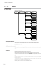
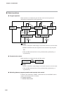
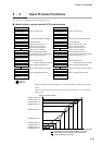
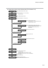
■ Model without carbon potential (CP) compensation
NOTE
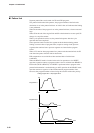
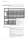
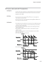
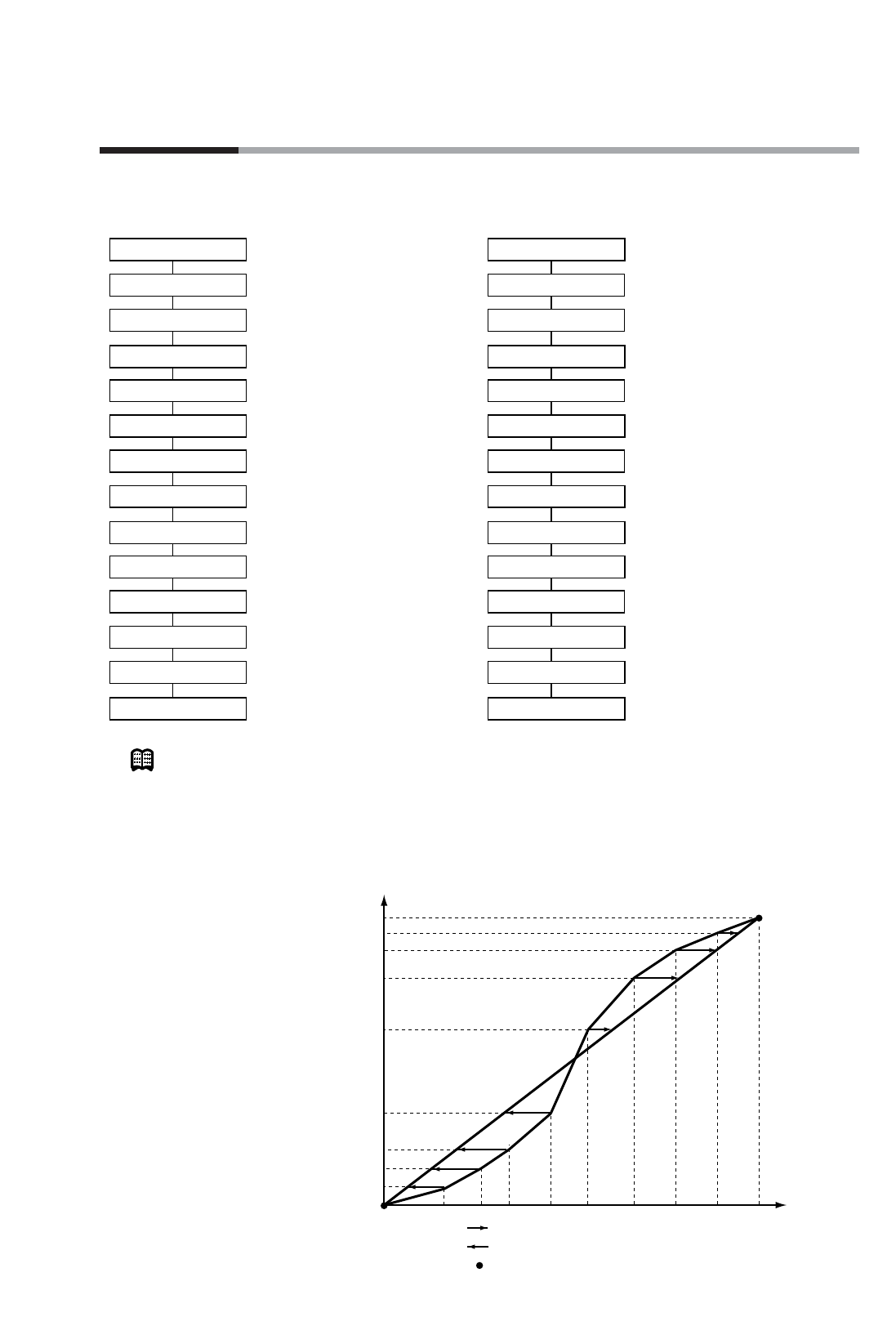
The use of equalizer (approximation by linearization table) is shown in the figure
below.
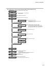
When a sensor with curved characteristics is used to measure PV, a linearization
table is used.
5-29
Chapter 5. FUNCTIONS
Analog input 1
Cold junction compensation
Wiring resistance compensation
A/D conversion
Input range type
Square-root extraction
Equalizer (approximation
by linearization table)
Upper and lower limit alarm
Temperature unit range
Upper and lower limit value scaling
Bias
PV (PV1)
Digital filter
PV shift
Setting: setup data C01
(For resistance temperature detector)
(For thermocouple)
Setting: setup data C07, C10
(For DC current or voltage)
Setting: setup data C08, C09
(For DC current or voltage)
Setting: setup data C04 to C06
(For thermocouple or resistance temperature detector)
Setting: setup data C02, C03
Setting: setup data C30
Variable parameters PA51 to PA70
Setting: variable parameter PA13
Setting: program setting PV shift item
Setting: variable parameter PA12
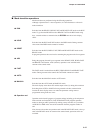
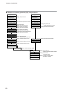
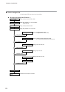
Analog input 2
Cold junction compensation
Wiring resistance compensation
A/D conversion
Input range type
Square-root extraction
Equalizer (approximation
by linearization table)
Upper and lower limit alarm
Temperature unit range
Upper and lower limit value scaling
Bias
PV2
Digital filter
PV shift
Setting: setup data C11
(For resistance temperature detector)
(For thermocouple)
Setting: setup data C17, C20)
(For DC current or voltage)
Setting: setup data C18, C19
(For DC current or voltage)
Setting: setup data C14 to C16
(For thermocouple or resistance temperature detector)
Setting: setup data C12, C13
Setting: setupdata C30
Variable parameters PA71 to PA9
0
Setting: variable parameter PA23
Setting: PV shift item in program setting
Setting: variable parameter PA22
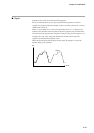
Actual PV
PV input (sensor output)
Correction point no. 1
Correction point no. 2
Correction point no. 3
Correction point no. 4
Correction point no. 5
Correction point no. 6
Correction point no. 7
Correction point no. 8
Correction point no. 9
Correction point no.10
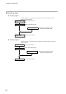
No.2
No.3
No.4
No.5
No.6
No.7
No.8
No.9
No.10
No.1
: (right facing arrow) indicates negative correction.
: (left facing arrow) indicates positive correction.
: (bullet) indicates 0 correction.