


iv
4-6 PV Input (Analog Input) Connection••••••••••••••••••••••••••••4-7
■ PV input CH1 connection•••••••••••••••••••••••••••••••••4-7
■ PV input CH2 connection•••••••••••••••••••••••••••••••••4-7
4-7 Control Output Connection ••••••••••••••••••••••••••••••••••4-9
4-8 Auxiliary Output Connection ••••••••••••••••••••••••••••••••4-10
■ Auxiliary Output CH1 Connection••••••••••••••••••••••••••4-10
■ Auxiliary Output CH2 Connection••••••••••••••••••••••••••4-10
4-9 Event Output (Open Collector Output) Connection ••••••••••••••••4-11
4-10 External Switch Input Connection ••••••••••••••••••••••••••••4-12
4-11 Communication Connection ••••••••••••••••••••••••••••••••4-13
■ RS-485 connection ••••••••••••••••••••••••••••••••••••4-13
■ RS-232C connection •••••••••••••••••••••••••••••••••••4-16
■ Connection to ST221 •••••••••••••••••••••••••••••••••••4-17
4-12 Isolation between Input and Output •••••••••••••••••••••••••••4-18
Chapter 5. FUNCTIONS
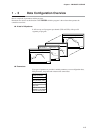
5-1 Data •••••••••••••••••••••••••••••••••••••••••••••••••••5-1
■ Data types••••••••••••••••••••••••••••••••••••••••••••5-1
5-2 Program Pattern ••••••••••••••••••••••••••••••••••••••••••5-2
■ Pattern ••••••••••••••••••••••••••••••••••••••••••••••5-2
■ Events ••••••••••••••••••••••••••••••••••••••••••••••5-5
■ PID group selection ••••••••••••••••••••••••••••••••••••5-16
■ Selection of output limiter group ••••••••••••••••••••••••••5-16
■ G.SOAK (Guarantee soak) •••••••••••••••••••••••••••••• 5-17
■ PV shift
•••••••••••••••••••••••••••••••••••••••••••••5-18
■ Repeat •••••••••••••••••••••••••••••••••••••••••••••5-19
■ PV start•••••••••••••••••••••••••••••••••••••••••••••5-20
■ Cycle ••••••••••••••••••••••••••••••••••••••••••••••5-21
■ Pattern link ••••••••••••••••••••••••••••••••••••••••••5-22
■ Tag ••••••••••••••••••••••••••••••••••••••••••••••••5-23
5-3 Mode •••••••••••••••••••••••••••••••••••••••••••••••••5-24
■ Mode types ••••••••••••••••••••••••••••••••••••••••••5-24
■ Mode transitions ••••••••••••••••••••••••••••••••••••••5-26
■ Mode transition operations ••••••••••••••••••••••••••••••5-27
■ Mode transition restrictions ••••••••••••••••••••••••••••••5-28
5-4 Input Process Functions •••••••••••••••••••••••••••••••••••5-29
■ Model without carbon potential (CP) compensation•••••••••••••5-29
■ Model with carbon potential (CP) compensation •••••••••••••••5-30
■ O
2 sensor check (model with CP compensation)
•••••••••••••• 5-31
5-5 Output Processing Functions •••••••••••••••••••••••••••••••5-32
■ Control output CH1 ••••••••••••••••••••••••••••••••••••5-32
■ Control output CH2 ••••••••••••••••••••••••••••••••••••5-34
■ Auxiliary output
•••••••••••••••••••••••••••••••••••••••5-36