


46
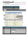
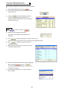
Monitoring Inverter Status [Monitor]
G
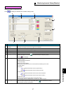
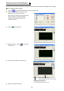
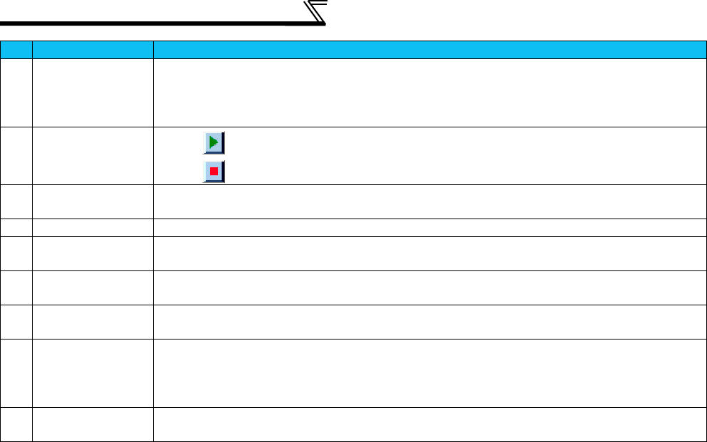
Trigger mode Selects the trigger mode.
Single ..............Displays one waveform by one shot.
Repeat............. Repeats single shots to display up to eight waveforms. (Since up to eight histories are
displayed, the oldest data is deleted when the ninth data is obtained.)
H
Collection of
waveform data
Clicking starts sampling data and displaying graphs.
Clicking stops sampling.
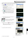
I
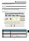
Cursor Displays the cursor to check the numerical value on the cursor or to check the maximum and minimum
values of the graph between cursors. (Refer to Cursor function, page 49.)
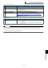
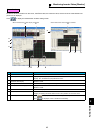
J
Gray display
Displays the background as white and the graph lines as black.
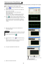
K
Waveform data
display
Displays waveform data as graphs.
L
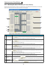
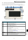
Setting of horizontal
axis scale
Sets the horizontal axis scale values.
M
Y-axis scale
optimization
Used to change the scale automatically so that the waveform of each channel is contained within the screen.
Analog data is displayed at about 80% of the graph display.
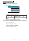
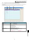
N
Setting of vertical
axis scale
Sets the vertical axis scale values. CH1 to CH3 can be set individually.
The setting is performed by selecting from the list or directly inputting into the input column.
The list displays five analog data, 1/10, 1/20, 1/100, 1/200, and 1/500 of the maximum value.
Offset can be also set.
O
Position move of
vertical axis 0
The position of 0 in the vertical axis scale can be moved.
No. Name Function and description