47
Monitoring Inverter Status [Monitor]
2
FUNCTIONS
Sets the condition of measurement start.
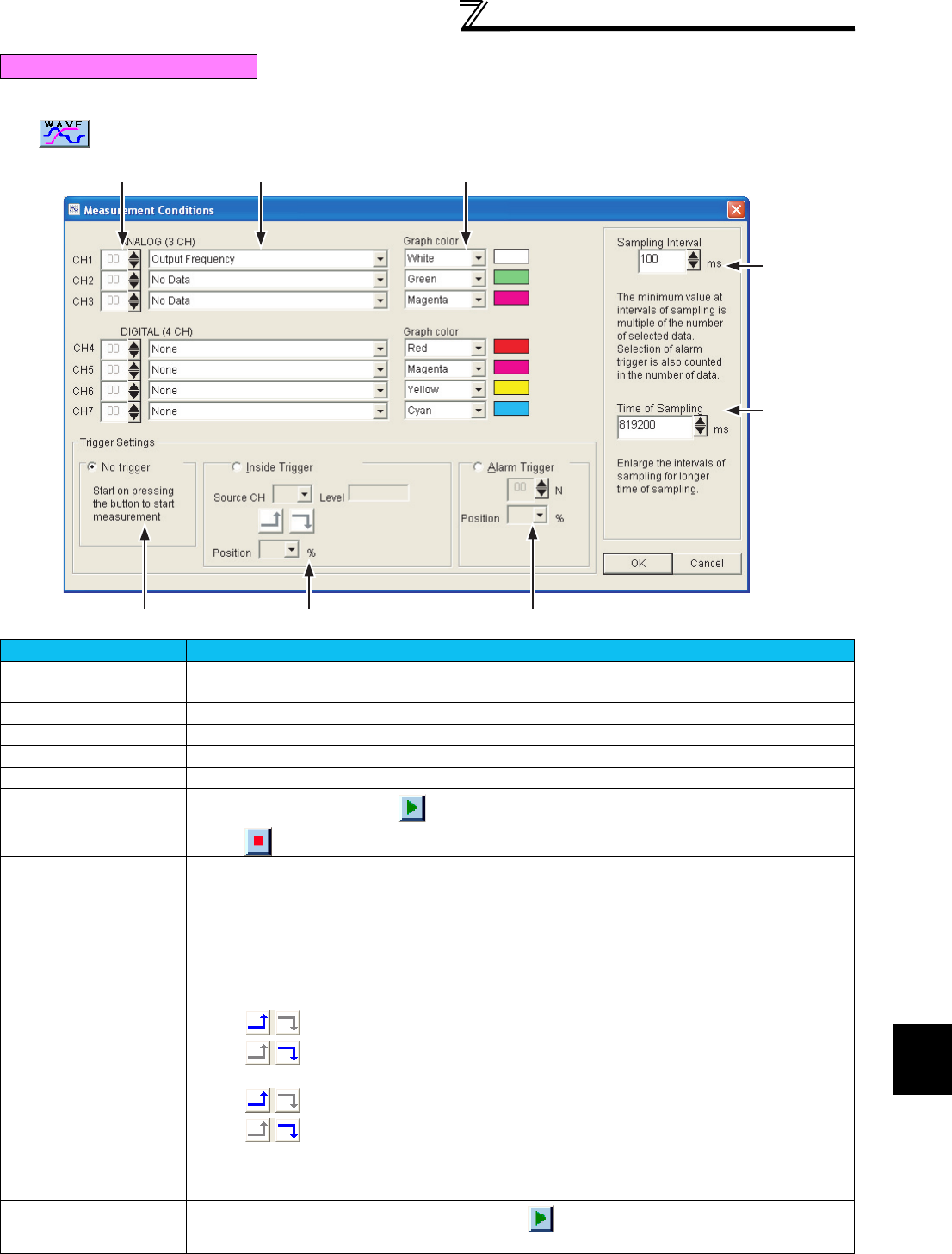
Click to display the measurement condition setting screen.
Measurement condition setting
No. Name Function and description
A
Station number
selection
Selects the inverter station number to be measured.
Up to 3CH for analog and up to 4CH for digital can be selected.
B
Data item selection
Selects the data item displayed as a graph.
C
Graph color
Selects the color of waveform displayed as a graph.
D
Sampling Interval
Sets the interval of data measurement.
E
Time of Sampling
Sets the time of data measurement.
F
No trigger
Selecting "No trigger" and clicking starts data sampling and displaying graphs.
Clicking stops sampling.
G
Inside trigger
Selecting the inside trigger starts measuring the data when the setting condition is met.
• Source CH setting
Selects the CH to be measured.
• Level value setting
Set the level value of trigger.
Selecting the analog data from CH1 to CH3 makes the level setting column valid.
• Condition setting
Digital data:
...Measurement starts when the signal starts up.
...Measurement starts when the signal shuts down.
Analog data:
...Measurement starts when the level value is exceeded.
...Measurement starts when the level value is underrun.
• Position setting
Select what % before the trigger position to start data sampling.
The set trigger position is displayed with a character of 'T' above the graph.
H
Alarm trigger
When the inverter outputs the alarm signal after clicking , the measurement is started.
Select the station number and the position.
AB C
D
E
FG H


