51
Monitoring Inverter Status [Monitor]
2
FUNCTIONS
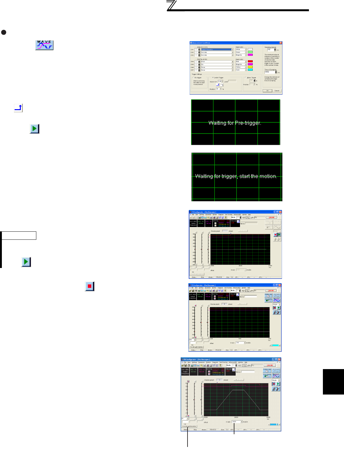
Oscilloscope measurement procedure example (monitoring output frequency, RUN signal and SU signal)
When measuring by inside trigger setting (Example: RUN signal startup)
(1) Clicking to display the Measurement Conditions
setting screen.
(2) Select "Output Frequency" from the CH1 list, "RUN" from
CH4, and "SU" from CH5.
Set the sampling interval and the sampling time.
Set the trigger setting.
Check the Inside Trigger, select "4" for the source CH, click
, and then set "10%" for the position.
After setting, click [OK] and return to the oscilloscope screen.
(3) When is clicked, the screen displays "Waiting for Pre-
trigger." and retrieve the data before trigger occurrence. After
the retrieval of the data, the screen displays " Waiting for
trigger, start the motion." and becomes the trigger waiting
condition.
(4) When the trigger condition is met (RUN signal startup), the
measurement is automatically started.
REMARKS
For this example, the sampling time is set to "20000ms" and the position
"10%", and therefore the startup of the RUN signal within 2000ms after
clicking is ignored, and the measurement is not started.
(5) Measuring stops by clicking or after the set sampling
time.
The data of 2000ms before the RUN signal startup and of
18000ms after the startup are displayed.
(6) The graph is adjustable for the better view.
(7) Data can be saved as a GPI file.
Adjusts the horizontal scale.
Input by selecting from the list or input directly.
Optimizes the vertical axis scale.
The adjustment to about 80%
of the oscilloscope screen can be made.
