


56
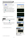
Inverter Failure Check [Diagnosis]
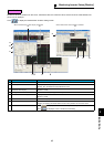
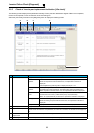
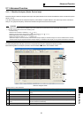
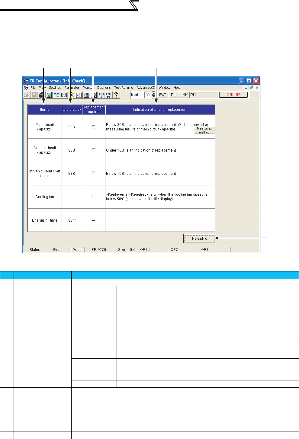
2.9.3 Check of inverter part replacement indication [Life check]
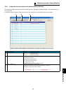
The following screen displays the replacement necessity of each part with deterioration degree of Main circuit capacitor,
Control circuit capacitor, Inrush current limit circuit and Cooling fan.
Select the [Life check] command in the [Diagnosis] menu to display the following screen.
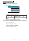
No. Name Function and description
A
Items Displays items to be diagnosed.
Main circuit
capacitor
Measured the main circuit capacitor capacitance at factory shipment as 100 %.
When the capacitance reduces below 85 %, the replacement indication is
displayed.
Click the [Measuring method] button to display the help of Pr.259.
Control circuit
capacitor
In the operating status, the control circuit capacitor life is calculated from the
energization time and temperature, and deterioration degree is displayed in %.
When capacitance reduces below 10 %, the replacement indication is displayed.
Inrush current limit
circuit
The number of contact (relay, contactor, thyristor) ON times is counted, and it is
counted down from 100% (1 million times) every 1%(10,000 times).
When 10 % (900,000 times) is reached, the replacement indication is displayed.
Cooling fan Detects the cooling fan speed.
When the cooling fan speed reduces below 50%, the replacement indication is
displayed.
Energization time Displays inverter cumulative energization time after factory shipment.
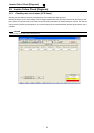
B
Life display Displays the life of each item in %.
C
Replacement required Displays replacement necessity of each part.
If items exceed the indication of replacement, the check box is checked, and the item line is displayed in
red.
D
Indication of time for
replacement
Explains the indication of replacement timing.
E
Rereading Reads the updated status from inverter to update the display.
ABC D
E