


Using the BayStack 350 10/100/1000 Series Switch
2-14
309979-A Rev 00
Verifying the Installation
When power is applied to the switch, power-on self-tests are run.
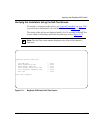
You can verify proper operation of the BayStack 350 switch by observing the
front-panel LEDs or by viewing the self-test results as displayed in the BayStack
350 switch Self-Test screen.
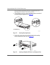
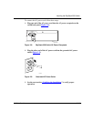
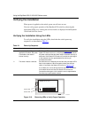
Verifying the Installation Using the LEDs
To verify the installation using the LEDs, check that the switch power-up
sequence is as described in Table 2-1
:
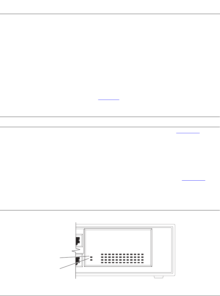
Figure 2-10. Observing LEDs to Verify Proper Operation
Table 2-1. Power-Up Sequence
Stage Description LED indication
1 Immediately after AC power is
applied to the switch, DC power
is available to the switch’s
internal circuitry.
The Power LED turns on within 5 seconds (Figure 2-10
). If the
Power LED does not turn on, verify that power is available at the
AC power outlet and that the power cable is fastened securely at
both ends. If the Power LED remains off, contact the sales agent
or the customer service representative from whom you
purchased the switch.
2 The switch initiates a self-test. As subroutines are initiated by the self-test, the port status LEDs
flash various patterns. When the switch passes the self-test
(within 10 seconds), the Status LED turns on (Figure 2-10
).
If a nonfatal error occurs during self-test, the Status LED blinks.
If the switch fails the self-test, the Status LED remains off.
Contact the sales agent or the customer service representative
from whom you purchased the switch.
Power LED
Status LED
BS35040A
350-24T Switch
BayStack
Status
Pwr
153
Activity
Activity
2119 23
10/100
10/100
1713 151179
2642220 241814 1612810