


Using the BayStack 350 10/100/1000 Series Switch
1-24
309979-A Rev 00
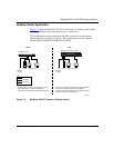
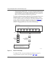
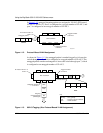
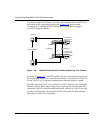
In Figure 1-12, untagged incoming packets are assigned to VLAN 3 (IP Protocol
VLAN = 3, PVID = 2). Port 5 is configured as a tagged member of VLAN 3, and
port 7 is configured as an untagged member of VLAN 3.
Figure 1-12. Protocol-Based VLAN Assignment
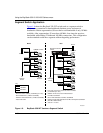
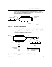
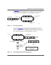
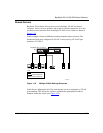
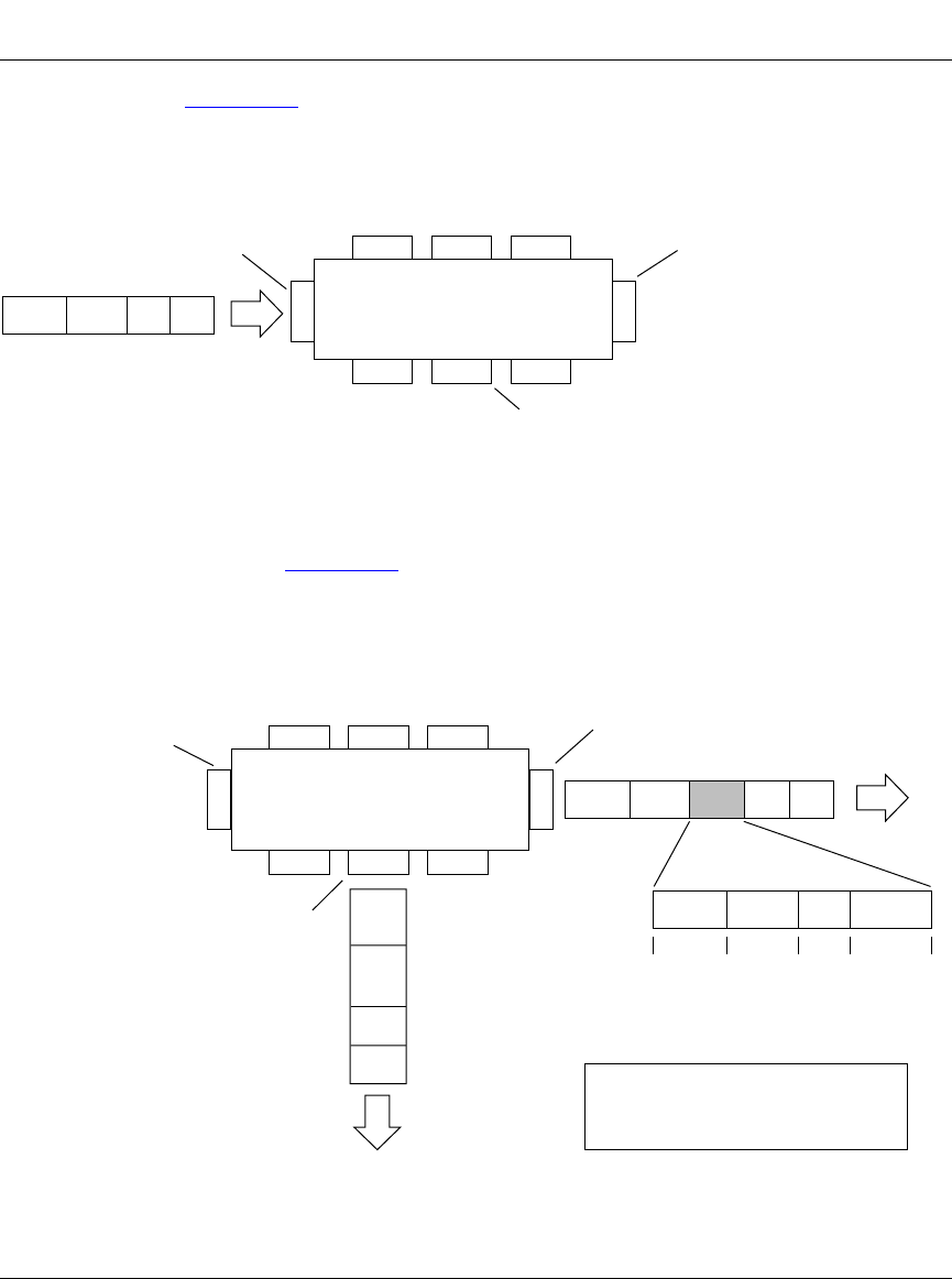
As shown in Figure 1-13, the untagged packet is marked (tagged) as it leaves the
switch through port 5, which is configured as a tagged member of VLAN 3. The
untagged packet remains unchanged as it leaves the switch through port 7, which
is configured as an untagged member of VLAN 3.
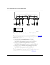
Figure 1-13. 802.1Q Tagging (After Protocol-Based VLAN Assignment)
Port 6
DASADataCRC
BS35011B
Port 7 Port 8
Port 1
Port 4
Port 5
Port 2 Port 3
802.1Q Switch
PVID = 2
Untagged packet
Untagged member
of VLAN 3
Tagged member
of VLAN 3
Before
IP Protocol VLAN = 3
BS35012B
Port 6 Port 7 Port 8
Port 1
Port 4
Port 5
Port 2 Port 3
802.1Q Switch
Key
Priority
CFI
VID
- User_priority
- Canonical format indicator
- VLAN identifier
PVID = 2
Tagged member
of VLAN 3
Untagged member
of VLAN 3
After
DA
SA
Data
CRC
(*Recalculated)
Outgoing
untagged packet
(unchanged)
DASADataCRC* Tag
VID = 3Priority
16 bits 3 bits 1 bits 12 bits
8100 CFI
IP Protocol VLAN = 3