Using the BayStack 350 10/100/1000 Series Switch
1-4
309979-A Rev 00
The 10BASE-T/100BASE-TX port connectors are configured as MDI-X
(media-dependent interface-crossover). These ports connect over straight cables to
the network interface controller (NIC) card in a node or server, similar to a
conventional Ethernet repeater hub. If you are connecting to another Ethernet hub
or Ethernet switch, you need a crossover cable unless an MDI connection exists
on the associated port of the attached device (see “MDI and MDI-X Devices” on
page E-2).
The switches use autosensing ports that are designed to operate at 10 Mb/s or at
100 Mb/s, depending on the connecting device. These ports support the IEEE
802.3u autonegotiation standard, which means that when a port is connected to
another device that also supports the IEEE 802.3u standard, the two devices
negotiate the best speed and duplex mode.
The 10BASE-T/100BASE-TX switch ports also support half- and full-duplex
mode operation (see “Connecting the 10BASE-T/100BASE-TX Ports” on
page 2-8).
The switch uses 10BASE-T/100BASE-TX RJ-45 port connectors to connect to
10 Mb/s or 100 Mb/s Ethernet segments or nodes.
See Appendix E, “Connectors and Pin Assignments” for more information about
the RJ-45 port connectors.
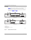
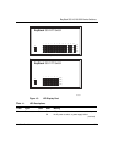
LED Display Panel
Figure 1-3
shows the LED display panels for the BayStack 350-24T and the
BayStack 350-12T models.
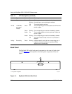
Refer to Table 1-1
for a description of the LEDs.
Note:
Use only Category 5 copper unshielded twisted pair (UTP) cable
connections when connecting 10BASE-T/100BASE-TX ports.
Note:
The LED display panel configuration for your switch may be different
than shown in Figure 1-3
, depending on the date of manufacturing (see the
note in “
10BASE-T/100BASE-TX Port Connectors” on page 1-3).


