


Using the BayStack 350 10/100/1000 Series Switch
1-2
309979-A Rev 00
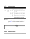
Front Panel
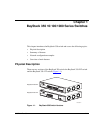
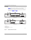
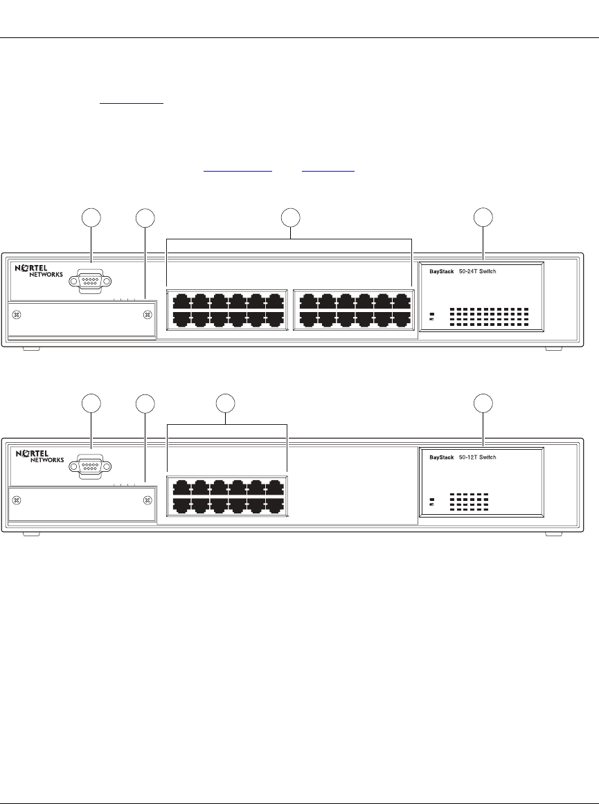
Figure 1-2 shows the front-panel configurations for the two BayStack 350 switch
models. Descriptions of the front-panel components follow the figures.
For a description of the components located on the back panel of the BayStack
350 switch, see “Back Panel
” on page 1-6.
Figure 1-2. BayStack 350 Switch Front Panels
Uplink/Expansion Module
2826 2725
Comm Port
Uplink/Expansion Module
16
Comm Port
13 1514
17 1913 15 21
18 2014 16 22 24
23
Status
Pwr
Pwr
Status
Activity
Activity
10/100
10/100
Activity
Activity
10/100
10/100
1
2
3
1
2
3 4
4
BayStack 350-24T
BayStack 350-12T
1
2
3
4
= Comm Port
= Uplink/Expansion slot
= 10BASE-T/100BASE-TX port connectors
= LED display panel
BS35002A
5713 9
682 4 10 12
11
5713 9
682 4 10 12
11
3
3