


312410-A Rev 00
Index-1
Numbers
10Base-T ports (ANH-8/DC), 2-13, 2-17, C-7
A
AN/DC
connecting to the power source, 1-18
dimensions, C-1
installing
in an electronic enclosure rack, 1-6
on a flat surface, 1-6
on a wall, 1-9
LEDs. See LEDs, AN/DC
POWER, 4-4
shipment contents, 1-1, 1-2
site requirements, 1-4
ANH-8/DC
configuring multiple, 2-14
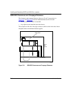
connecting to the power source, 2-26
connectors, C-2
AUI, C-7
console, C-10
UTP, C-7
dimensions, C-1
installing, 2-6 to 2-11
shipment contents, 2-2
site requirements, 2-5
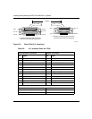
AUI port
cables, C-6
connecting drop cable, 2-12
Partition LED, 4-7
pin assignments, C-6, C-8
specifications, C-6
automatic polarity adjustment, C-7
B
BOOT LED
AN/DC, 4-4
ANH-8/DC, 4-6
booting, 3-11, 4-10
BootP server, 3-2, A-3
brackets, flange
installing on AN/DC, 1-7
installing on ANH-8/DC, 2-7, 2-10
C
cables
AUI, C-6
console
PC, 1-15, 2-22
terminal, 1-12, 1-14, 2-20, 2-22
console/modem kit
for AN/DC, 1-2
for ANH-8/DC, 2-2
in shipping package, 1-2
installing
AN/DC console, 1-12
ANH-8/DCconsole, 2-20
Ethernet AUI, 2-12
Ethernet UTP, 2-13, 2-17
ISDN, 2-19
LAN, 2-12 to 2-17
synchronous, 2-18
WAN, 2-18
locating, 1-3
modem, 1-16, 2-23
network
connecting to AN/DC, 1-11
connecting to ANH-8/DC, 2-12 to 2-19
Index