


Installing the ANH-8/DC
312410-A Rev 00
2-27
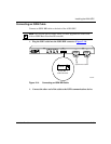
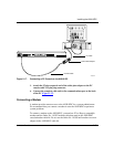
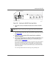
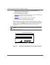
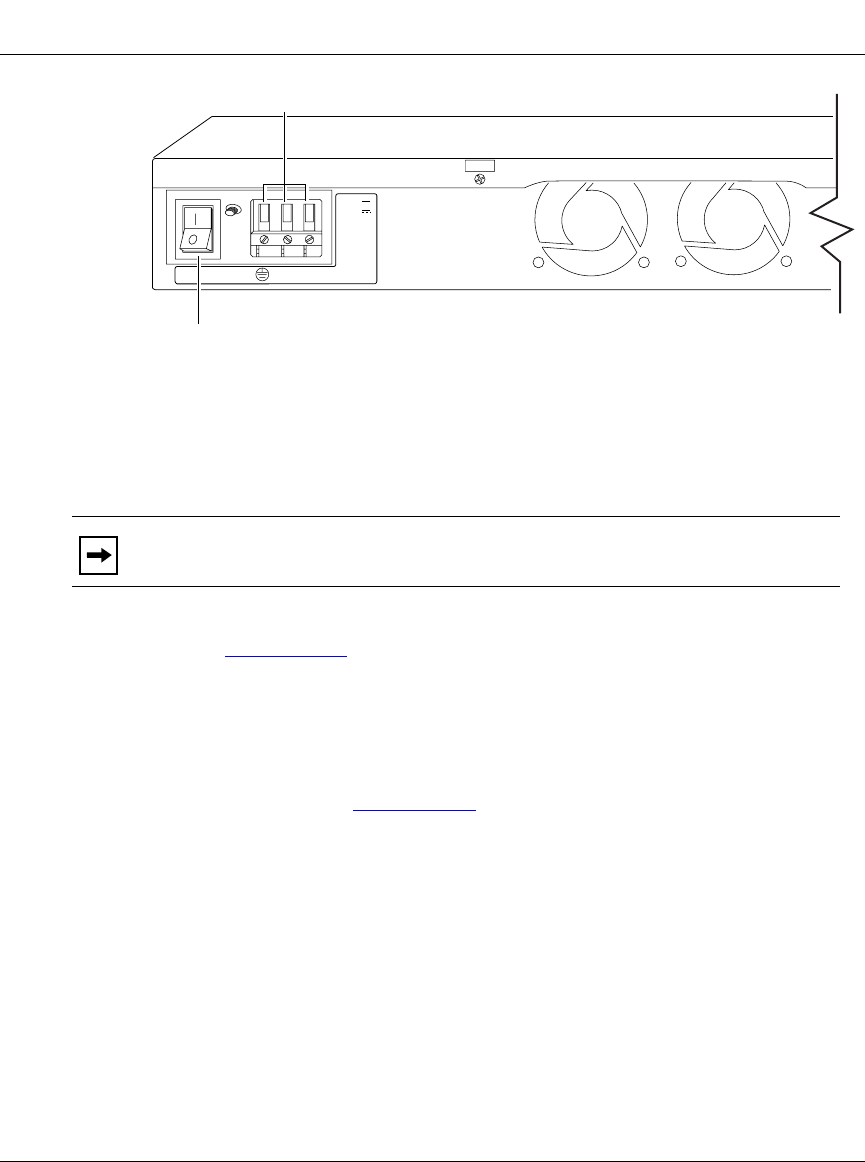
Figure 2-20. Attaching the ANH-8/DC Power Input Cables
6.
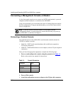
Strip 3/8 in. (10 mm) of insulation from the end of a #16 or #18 AWG
cable.
7.
Insert the stripped end of the cable into the RTN terminal block, the plus
lead (Figure 2-20)
.
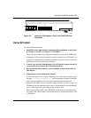
8.
Tighten the screw beneath the RTN terminal block to establish the
electrical connection.
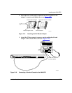
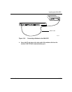
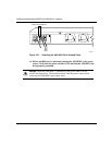
9.
Connect an earth ground wire to either the leftmost terminal block, or to
the grounding stud located between the power switch and the power
module connector (Figure 2-21)
.
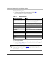
We recommend using the same wire gauge (or greater) for the earth ground as
that used for connection to the power source. That is, if connection to the
power source uses #16 AWG cable, use #16 AWG cable for the ground. If
connection to the power source uses #18 AWG cable, use #18 or #16 AWG
cable for the ground.
Use a #6 ring terminal when the connecting to the grounding stud.
Note:
Make certain to use the same wire gauge as that used for the minus lead.
AN0094A
Power switch OFF (0)
DC power terminals (3)
RTN -VDC
-48VDC
-60VDC
1.5A