4-20
ENG
VALVES AND VALVE SPRINGS
NOTE:
NOTE:
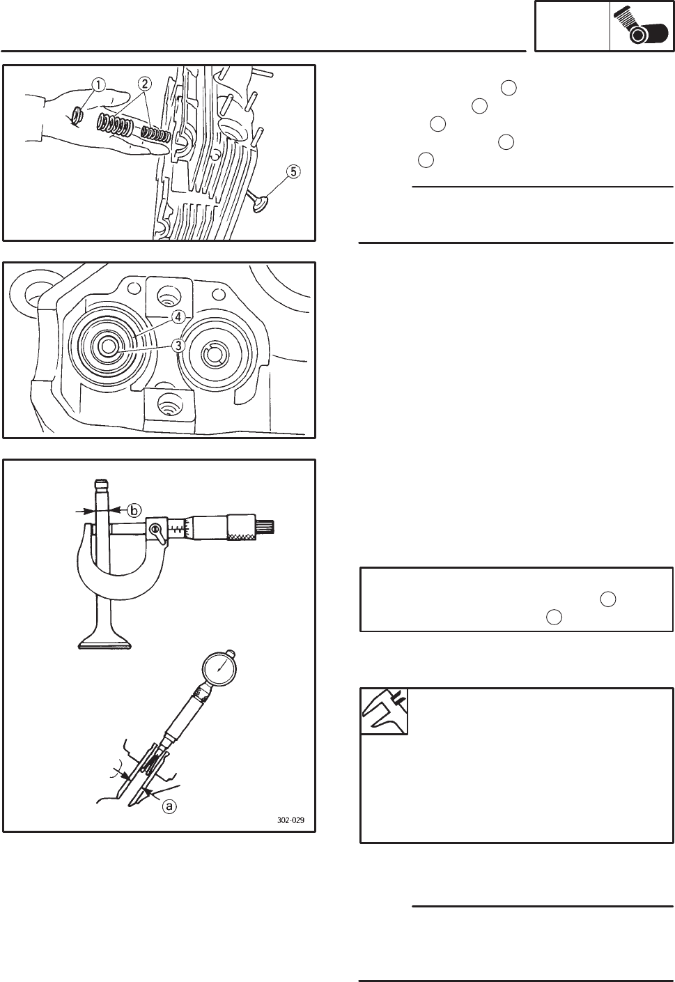
4. Remove:
Supper spring seat
1
Svalve springs
2
Soil seal
3
Slower spring seat
4
Svalve
5
Identify the position of each part very carefully
so that it can be reinstalled in its original place.
EAS00239
CHECKING THE VALVES AND VALVE GUIDES
The following procedure applies to all of the
valves and valve guides.
1. Measure:
Svalve-stem to valve guide clearance
Valve-stem to valve-guide clearance =
Valve guide inside diameter
a
–
Valve stem diameter
b
Out of specification ! Replace the valve
guide.
Valve-stem to valve-guide clear-
ance
Intake
0.010 X 0.037 mm
Limit: 0.08 mm
Exhaust
0.025 X 0.052 mm
Limit: 0.10 mm
2. Replace:
Svalve guide
To ease valve guide removal and installation,
and to maintain the correct fit, heat the cylinder
head to 100_C (212_F) in an oven.


