


7-2
ELEC
SWITCHES
B
B
CAUTION:
NOTE:
NOTE:
EAS0010
SWITCHES
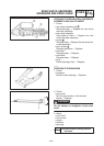
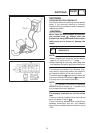
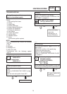
CHECKING SWITCH CONTINUITY
Check each switch for continuity with the pocket
tester. If the continuity reading is incorrect,
check the wiring connections and if necessary,
replace the switch.
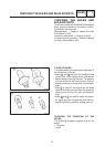
Never insert the tester probes into the cou-
pler terminal slots
1
. Always insert the
probes from the opposite end of the coupler,
taking care not to loosen or damage the
leads.
Pocket tester
90890-03112
SBefore checking for continuity, set the pocket
tester to “0” and to the “Ω 1” range.
SWhen checking for continuity, switch back and
forth between the switch positions a few times.
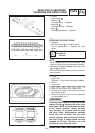
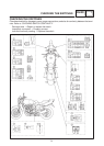
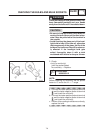
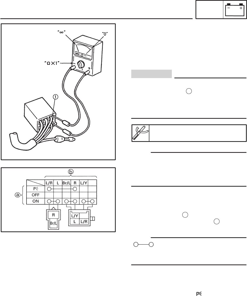
The terminal connections for switches (e.g.,
main switch, engine stop switch) are shown in
an illustration similar to the one on the left.
The switch positions
a
are shown in the far left
column and the switch lead colors
b
are shown
in the top row in the switch illustration.
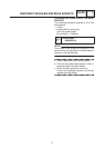
“
” indicates a continuity of electricity
between switch terminals (i.e., a closed circuit
at the respective switch position).
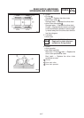
The example illustration on the left shows
that:
There is continuity between blue/red and red
when the switch is set to “
”.
There is continuity between blue/red and blue,
between brown/blue and red, and between
blue/yellow and black when the switch is set to
“ON”.