


7-36
A B
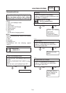
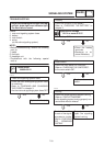
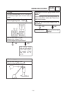
Replace the left han-
dlebar switch.
NO
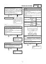
2. Turn signal switch
SCheck the turn signal for continuity.
Refer to “CHECKING THE SWITCHES”.
SIs the turn signal switch OK?
YES
The wiring circuit
from the main switch
to the flasher relay
coupler (flasher relay
side) is faulty and
must be repaired.
NO
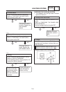
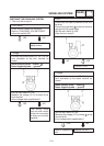
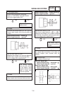
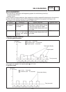
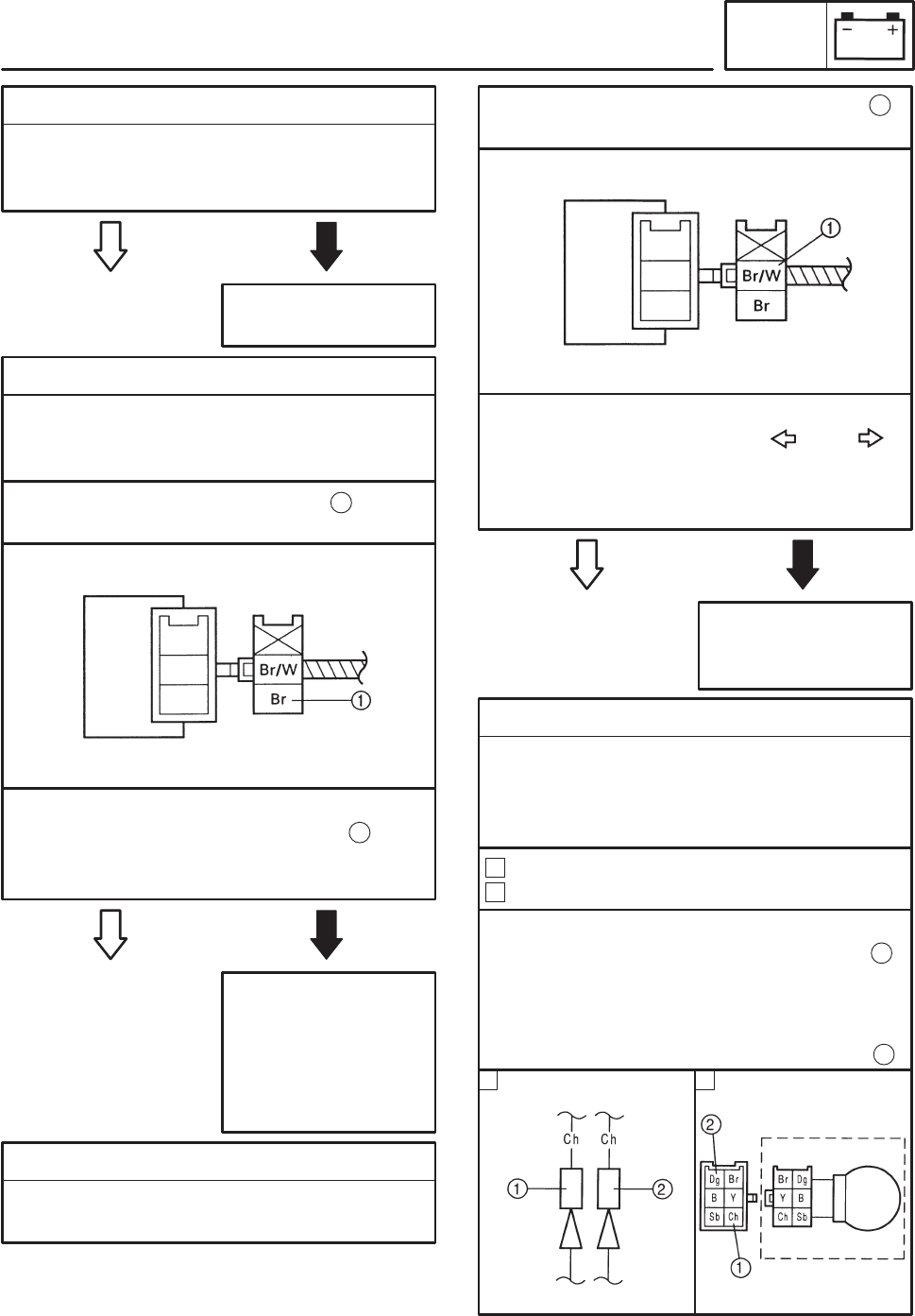
3. Voltage
SConnect the pocket tester (DC 20 V) to the
flasher relay coupler (wire harness side) as
shown.
YES
Tester positive probe ! brown
Tester negative probe ! ground
1
SSet the main switch to “ON”.
SMeasure the voltage (12 V) of brown at the
flasher relay coupler (wire harness side).
SIs the voltage within specification?
1
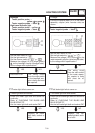
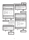
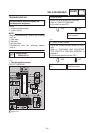
4. Voltage
SConnect the tester (DC 20 V) to the flasher
relay coupler (wire harness side) as shown.
The flasher relay is
faulty and must be re-
placed.
NO
YES
1
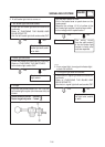
SSet the main switch to “ON”.
SSet the turn signal switch to “ ” or “ ”.
SMeasure the voltage (12 V) or brown/white at
the flasher relay coupler (wire harness side).
SIs the voltage within specification?
Tester positive probe ! brown/white
Tester negative probe ! ground
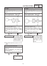
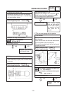
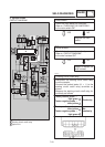
5. Voltage
SConnect the pocket tester (DC 20 V) to the
turn signal light connectors or the meter as-
sembly coupler (wire harness side) as
shown.
Turn signal light
Turn signal indicator light
A
B
Left turn signal light
Tester positive probe ! chocolate
Tester negative probe ! ground
Right turn signal light
Tester positive probe ! dark green
Tester negative probe ! ground
1
2
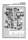
SIGNALING SYSTEM
ELEC