


7-37
SIGNALING SYSTEM
ELEC
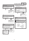
Replace the neutral
indicator light bulb,
socket or both.
NO
YES
The wiring circuit
from the turn signal
switch to the turn sig-
nal light connector is
faulty and must re-
paired.
NO
This circuit is OK.
EAS00800
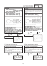
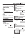
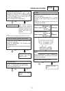
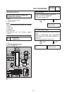
4. The neutral indicator light fails to come on.
1. Neutral indicator light bulb and socket
SCheck the neutral indicator light bulb and
socket for continuity.
Refer to “CHECKING THE BULBS AND
BULB SOCKETS”.
SAre the neutral indicator light bulb and socket
OK?
YES
SSet the main switch to “ON”.
SSet the turn signal switch to “ ” or “ ”.
SMeasure the voltage (12 V) of chocolate
or dark green at the turn signal light con-
nector (wire harness side).
SIs the voltage within specification?
1
2
Replace the neutral
switch.
NO
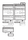
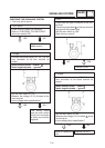
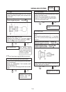
2. Neutral switch
SCheck the neutral switch for continuity.
Refer to “CHECKING THE SWITCHES”.
SIs the neutral switch OK?
YES
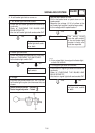
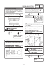
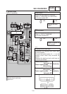
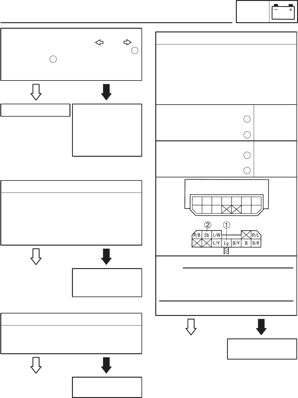
3. Diode
SDisconnect the starting circuit cutoff relay
from the coupler.
SConnect the pocket tester (Ω 1) to the
starting circuit cutoff relay terminals as
shown.
SMeasure the starting circuit cutoff relay for
continuity as follows.
YES
Replace the relay
unit.
NO
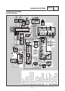
Tester positive probe !
light green
Tester negative probe !
sky blue
1
2
Continuity
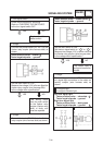
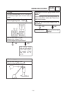
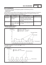
NOTE:
When you switch the “–” and “+” leads of the
digital pocket tester the readings in the above
chart will be reversed.
SAre the tester readings correct?
EAS00760
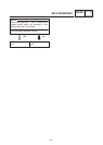
Tester positive probe !
sky blue
Tester negative probe !
light green
2
1
No
continuity