


7-16
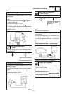
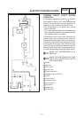
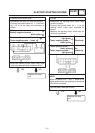
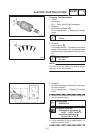
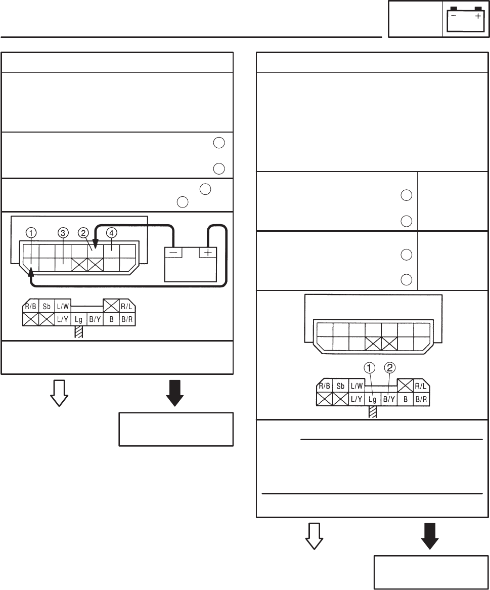
4. Starting circuit cutoff relay
SDisconnect the relay unit from the coupler.
SConnect the pocket tester (Ω 1) and bat-
tery (12 V) to the relay unit terminals as
shown.
YES
Replace the relay
unit.
NO
Battery positive terminal ! red/black
Battery negative terminal !
black/yellow
1
2
Tester positive probe ! blue/white
Tester negative probe ! black
3
4
SDoes the starting circuit cutoff relay have
continuity between black and blue/white?
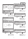
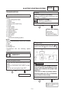
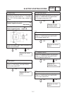
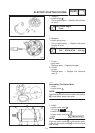
5. Diode
SDisconnect the starting circuit cutoff relay
from the coupler.
SConnect the pocket tester (Ω 1) to the
starting circuit cutoff relay terminals as
shown.
SMeasure the starting circuit cutoff relay for
continuity as follows.
YES
Replace the relay
unit.
NO
Tester positive probe !
light green
Tester negative probe !
black/yellow
1
2
Continuity
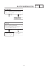
NOTE:
When you switch the “–” and “+” leads of the
digital pocket tester the readings in the above
chart will be reversed.
SAre the tester readings correct?
EAS00760
Tester positive probe !
black/yellow
Tester negative probe !
light green
2
1
No
continuity
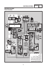
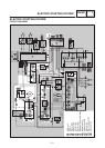
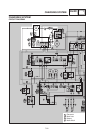
ELEC
ELECTRIC STARTING SYSTEM
EAS00759