


7-39
SIGNALING SYSTEM
ELEC
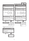
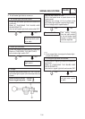
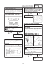
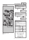
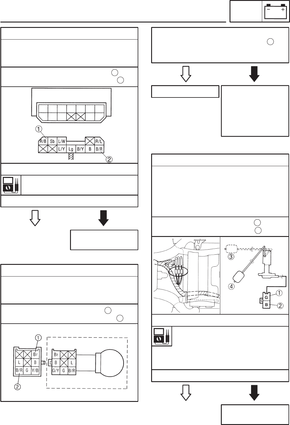
4. Starting circuit cutoff relay
SDisconnect the relay unit from the coupler.
SConnect the pocket tester (Ω 1) to the relay
unit terminals as shown.
Relay unit resistance
8.2 Ω at 20_C
Tester positive probe ! red/blue
Tester negative probe ! brack/red
SMeasure the relay unit resistance.
SIs the relay unit OK?
Replace the starting
circuit cutoff relay.
NO
YES
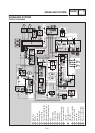
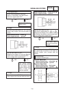
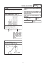
5. Voltage
SConnect the pocket tester (DC 20 V) to the
meter assembly coupler (wire harness side)
as shown.
Tester positive probe ! brown
Tester negative probe ! black/red
1
2
SSet the main switch to “ON”.
SMeasure the voltage (12 V) of brown and
black/red at the meter assembly coupler.
SIs the voltage within specification?
YES
The wiring circuit
from the main switch
to the meter assem-
bly coupler is faulty
and must be re-
paired.
NO
This circuit is OK.
EAS00804
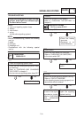
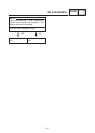
6. The fuel level gauge fails to operate.
1
Replace the fuel
sender.
NO
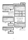
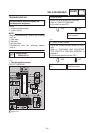
1. Fuel sender
SDisconnect the fuel sender coupler from the
wire harness.
SDrain the fuel from the fuel tank and remove
the fuel sender from the fuel tank.
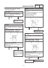
SConnect the pocket tester to the fuel sender
coupler as shown.
YES
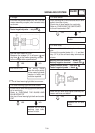
Tester positive probe ! green
Tester negative probe ! black
1
SIs the fuel sender OK?
2
Fuel sender resistance (up position)
4 X 10 Ω at 20_C
Fuel sender resistance (down posi-
tion)
90 X 100 Ω at 20_C
SMeasure the fuel sender resistance.
1
2