


5-12 Agilent E5250A User’s Guide, Edition 9
Controlling the E5250A
Switch Control Basics
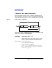
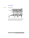
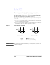
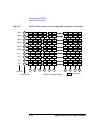
Figure 5-2 Example of Bias Mode
Figure 5-2 shows an example. Input port 2 is the input Bias Port. When the Bias
Mode is turned ON, all bias enabled output ports (that are not connected to other
input ports) are connected to the input Bias Port. So, the output ports that are
connected to input port 1 and 3 are not connected to the input Bias Port.
Close
Open
Connect to Bias port
Connect to Input 1
Connect to Input 3
Input 01
Input 03
Input 02
Bias Port
Input 10
Output Port