4-6 Agilent E5250A User’s Guide, Edition 9
Setting up Measurement Environment
Mounting Connectors Directly
Mounting Connectors Directly
Previous sections described the information to use the available accessories, also the
16495 Installation Guide provides the information how to install connector plates
on the shielding box. However, you may need to directly mount connectors on your
own connector plate or test fixture.
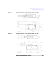
In this case, you need to make connector holes and directly mount the connectors
yourself. This section has dimension information about the holes you need to make.
Do the following:
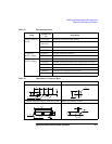
1. Select the appropriate parts for your situation. Refer to Table 4-1.
2. Make holes and mount the connectors. Refer to Table 4-2.
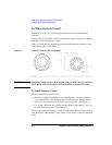
For kelvin connection, use the 16494B Kelvin cable. Kelvin cable requires the
kelvin triaxial connector which has two connector holes and three screw holes.
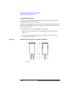
3. Make interlock circuit as shown in “To Make Interlock Circuit” on page 4-8.
4. Make cable connection between connector and DUT (device under test). Refer
to “To Connect Connectors to DUT” on page 4-13.
Table 4-1 lists the parts required to mount connectors on your shielding box. From
this table, select the parts that you need to mount. Quantity of parts depends on your
site.


