Agilent E5250A User’s Guide, Edition 9 5-17
Controlling the E5250A
Switch Control Basics
Auto Configuration Mode
To use this mode, the E5252A must be installed in the E5250A slots continuously
from slot1 (slots 1,2; or slots 1,2,3; or slots 1,2,3,4).
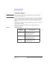
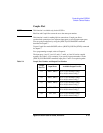
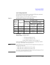
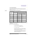
To specify a channel, you use five digits as shown in Table 5-6.
Table 5-6 Specifying E5252A Channels in Auto Config. Mode
Card Number: One digit: always 0.
Channel Number: Four digits: XXYY.
• XX: input port number (01 to 10).
• YY: output port number (01 to 48).
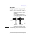
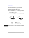
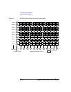
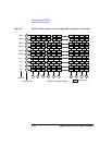
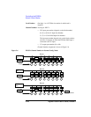
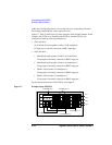
Channel Number assignment is shown in Figure 5-5.
In the Auto Configuration mode, you can omit any zeros at beginning of channel.
For example, channel 00101 can be expressed by 101.
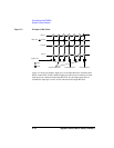
NOTE For the following two cases, three ports share one input path. Do not specify two of
the input ports at same time.
• SMU5, HF1, and CV1 (Input Port No. 05, 07, and 09)
• SMU6, HF2, and CV2 (Input Port No. 06, 08, and 10)
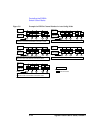
For example, if you specify input port 05, then you cannot specify input ports 07 and
09. You can specify 05 and 06 at the same time:
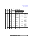
Slot No.
(E5252A
is
installed)
Configuration
One Channel: 5 digits
Card Number
(first 1 digit)
Channel Number: 4 digits
Input Port No.
(next 2 digits)
Output Port No.
(last 2 digits)
110×12 Matrix 0 01 to 10 01 to 12
1 and 2 10×24 Matrix 0 01 to 10 01 to 24
1 to 3 10×36 Matrix 0 01 to 10 01 to 36
1 to 4 10×48 Matrix 0 01 to 10 01 to 48


