


4-2 Agilent E5250A User’s Guide, Edition 9
Setting up Measurement Environment
This chapter explains how to connect your instruments to Agilent E5250A input,
and how to connect the E5250A output to your wafer prober or test fixture.
You can connect the E5250A output (E5252A or E5255A) to your prober or fixture
in the following three ways:
• Via the available connector plates.
• (For E5255A only) Directly using Agilent 16494E coaxial cable.
• Via connectors that you mount directly on your own connector plate or test
fixture.
This chapter explains how to do this in the following sections:
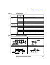
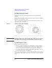
• “Connector Plates” introduces connector plates available for the plug-in card.
For installing the connector plates on your shielding box for prober or fixture,
refer to Agilent 16495 Installation Guide.
• “Connecting 8-Channel Shielded Coaxial Cable” explains how to use the
16494E coaxial cable, which is used to directly connect the E5255A output to
the DUT, DUT socket, or any fixture you want without using a connector plate.
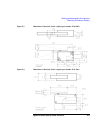
• “Mounting Connectors Directly” describes connector hole dimensions for
mounting connectors directly on your own connector plate or test fixture, and
describes the information to connecting the connectors to prober, socket or DUT.
• “Connecting the E5250A Input” explains how to connect instruments to the
E5250A input.
• “Connecting the E5250A Output” describes the information to connect the
plug-in card output to a connector plate, connectors on your own shielding box
and so on.
• “Measurement Cable Length” is a reference for deciding total cable length at
your site by calculating the total guard capacitance according to the cable length
from instrument to Device Under Test (DUT).