


Agilent E5250A User’s Guide, Edition 9 9-25
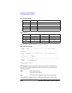
Executing Sample Programs
HCI Measurement Program
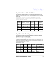
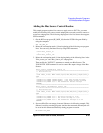
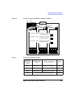
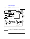
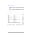
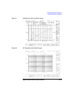
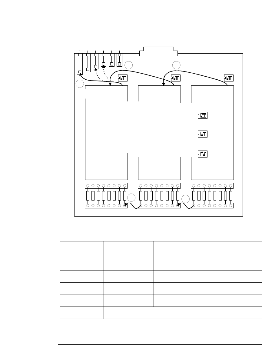
Figure 9-3 Internal Connections and DIP SW Settings for E5255As
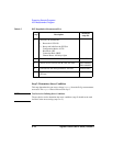
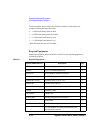
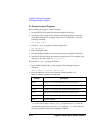
Table 9-7 E5250A Input/Output Connection
4155/4156
Measurement
Port
E5250A Input
Port
E5255A Output Port DUT
SMU 1 SMU INPUT 1 Output 1 to 24 (SLOT 1) Gate
SMU 3 SMU INPUT 3 Output 25 to 48 (SLOT 2) Drain
SMU 4 SMU INPUT 4 Output 49 to 72 (SLOT 3) Sub
GNDU (directly connected to Connector Plate) Source
IVin1 cable
IVin3 cableIVin2 cable
SW1 SW2
SW3
S
M
U
1
S
M
U
3
S
M
U
4
1
2 3
IVout1 IVout2
1 2 3 4 5 6 7 8
9 10 11 12 13 14 15 16 17 18 19 20 21 22 23 24
4
5
For E5255A in Slot 1: Connect IVin1 to SMU1, and
set SW1/SW2/SW3 to
For E5255A in Slot 2: Connect IVin1 to SMU3, and
set SW1/SW2/SW3 to
For E5255A in Slot 3: Connect IVin1 to SMU4, and
set SW1/SW2/SW3 to