1-4 Agilent E5250A User’s Guide, Edition 9
Introduction
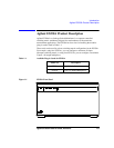
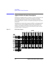
Agilent E5250A Product Description
Front Panel Tour
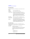
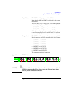
The E5250A has 2 hard keys and 4 LED indicators on the front panel as shown in
Figure 1-1.
LINE key Used to turn the E5250A on or off.
Line LED Turns on when the E5250A is turned on.
Local/Self Test key If "Remote" LED is on, pressing this key releases the
E5250A from remote GPIB control by an external controller.
If "Remote" LED is off, pressing this key executes the Relay
Test. Before pressing this key, make sure the Relay Test
Adapter is connected. For details of Relay Test, refer to
Chapter 3. During Relay Test execution, the LED in this key
is ON.
Remote LED Turns on when the E5250A is in the GPIB remote status.
System Fail LED Turns on if system error occurs in the E5250A. Contact your
nearest Agilent Technologies Service Center.
Fail LED Turns on if the E5250A fails Self-test (including Relay Test).
If this LED turns on after executing Relay Test, a plug-in
card may be defective. And if this LED turns on after turning
the E5250A on again, the E5250A is defective. If so, contact
your nearest Agilent Technologies Service Center.
Rear Panel Tour
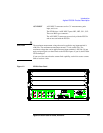
Rear panel of the E5250A is shown in Figure 1-2. The E5250A has 4 slots for
installing plug-in cards, and 10 input connectors for connecting measurement cables
from instruments.
SMU INPUT SMU INPUT connectors are for semiconductor dc
characteristics measurements.
The E5250A has six SMU INPUT ports, which are triaxial type
connectors. The connectors can also be used for a maximum
three Kelvin connection inputs by coupling two ports as
follows:
• SMU INPUT 1 and 2
• SMU INPUT 3 and 4
• SMU INPUT 5 and 6


