


Agilent E5250A User’s Guide, Edition 9 4-17
Setting up Measurement Environment
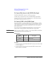
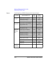
Connecting the E5250A Input
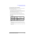
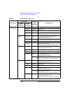
In the table above,
• AUX means CV1, CV2, HF1, or HF2 connector.
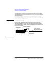
• The E5250A does not have input connectors for the interlock. Connect directly
from instrument to the connector plate which has an interlock connector.
• Can't use Agilent 41422A/41423A (HCU/HVU) of the 4142B with the E5250A.
• To connect instrument output that uses banana plug to AUX connector, use Dual
Banana plug to BNC Adapter (Agilent part number 1251-2277).
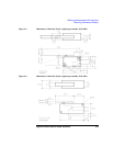
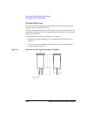
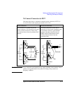
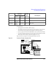
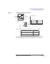
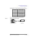
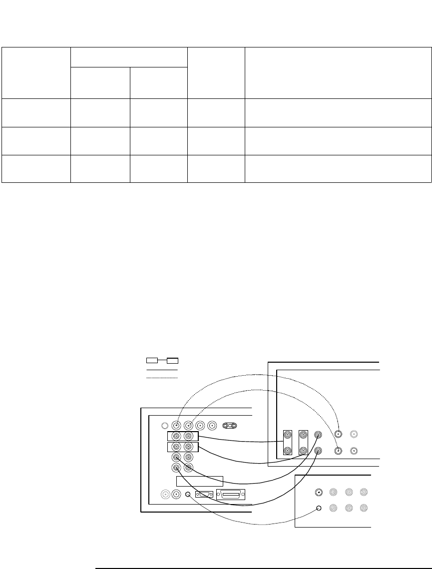
Figure 4-6 shows an example of connecting the E5250A to the 4156.
Figure 4-6 Connection Example with Agilent 4156
C
Measurement
C Meter High, Low CV1 and 2 BNC cable
Pulse Input Pulse
Generator
OUTPUT HF1 or 2 BNC cable
Bias Input Power
Supply
OUTPUT AUX1 to 4 BNC cable
Application
Instrument
E5250A
Input
Connector
Cable Required
Agilent
Model No.
Output
Connector
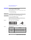
Agilent 4156
SMU
AUX
Connector Plate
Agilent E5250A
INTLK
GNDU
Kelvin Triaxial Cable
BNC Cable
Triaxial Cable
INTLK Cable