6-16 Agilent E5250A User’s Guide, Edition 9
Programming the E5250A
Programming Examples
Bias Mode Example
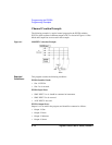
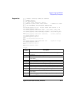
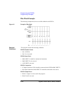
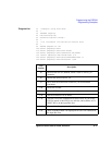
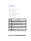
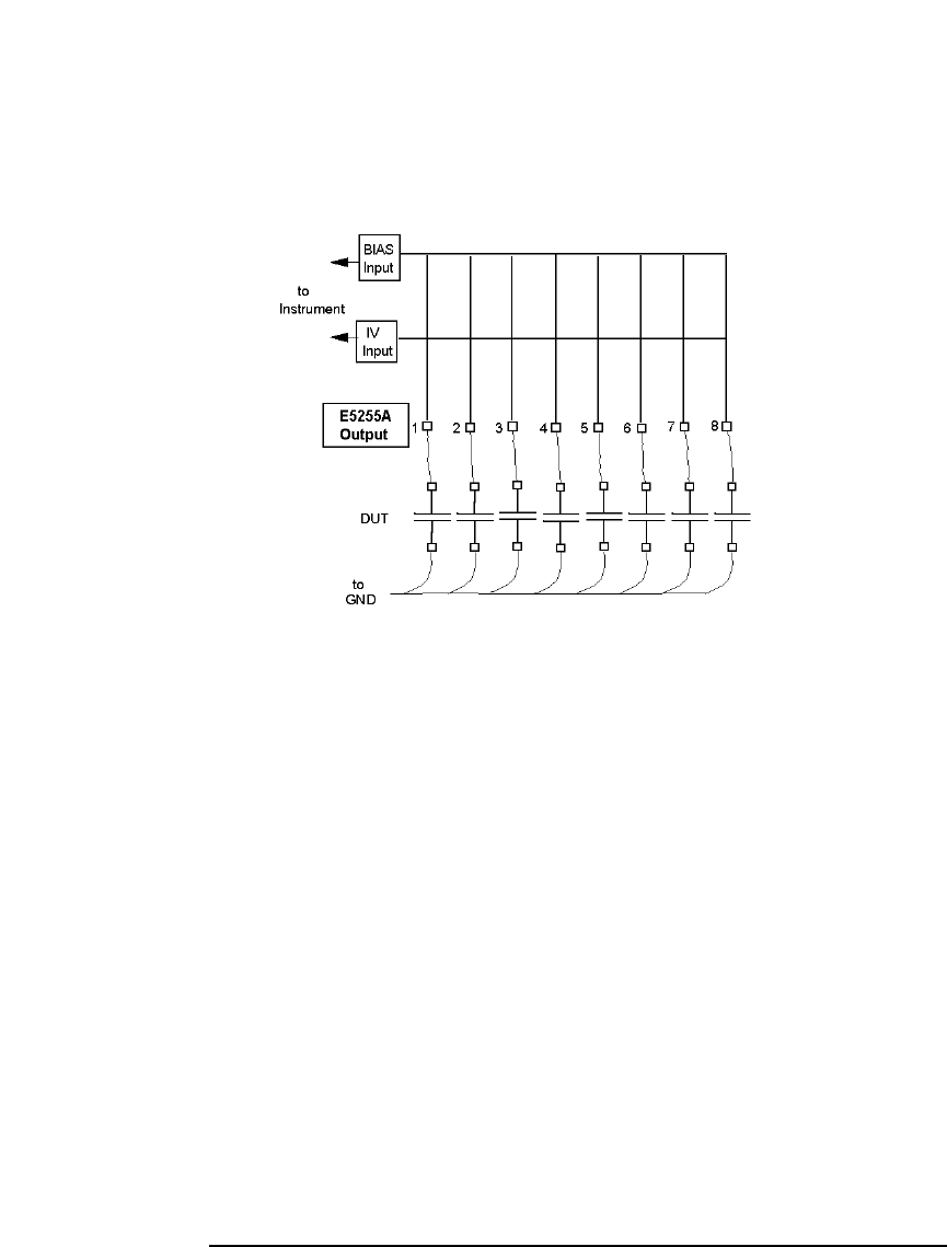
The following example shows how to use Bias Mode for the E5255A.
Figure 6-2 Example of Bias Mode
Required
Conditions:
This program assumes the following conditions.
E5250A Installed Cards:
• Slot 1: E5255A
• Slot 2 to 4: not used.
E5250A Input Ports:
• SMU INPUT 1: should be connected to instrument.
• SMU INPUT 2 to 6: not used.
• AUX INPUTs: not used.
E5255A Connection:
• IV Input Connection: IVin1 should be connected to the E5250A SMU INPUT 1.
• Bias Input Connection: BIAS INPUT 51 should be connected to bias source.
E5255A Output Ports:
• Block 1: outputs 1 to 8 are used in the program.
• Block 2 and 3: not used.


