


5-24 Agilent E5250A User’s Guide, Edition 9
Controlling the E5250A
Switch Control Basics
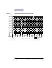
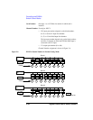
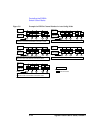
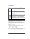
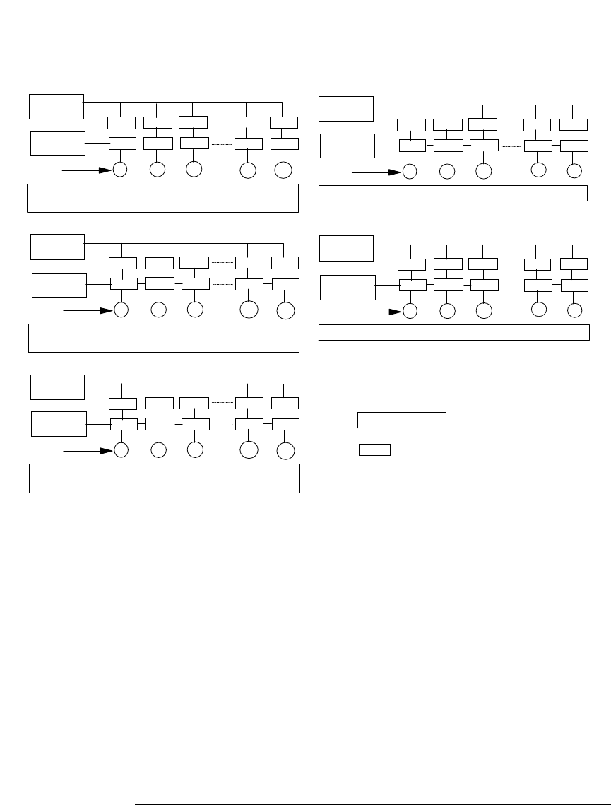
Figure 5-8 Example for E5255A Channel Number in Auto Config. Mode
XXXX
: Channel Number
Made from Cards in Slot #1 and #2.
Block #1 to 3 of each card should be connected in series.
Made from Block #1 of Cards in Slot #3 and #4.
Block #1 of each card should be connected in series.
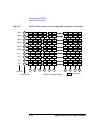
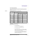
Made from Block #3 of Card in Slot #3.
Made from Block #3 of Card in Slot #4.
1
48
47
32
BIAS Input
(11)
IV Input
SMU1 (01)
Output
0101
0102
0103
0147 0148
1101
1102
1103
1147
1148
1
16
15
32
BIAS Input
(13)
IV Input
SMU3 (03)
Output
0301
0302
0303
0315 0316
1301
1302
1303
1315 1316
Made from Block #2 of Cards in Slot #3 and #4.
Block #2 of each card should be connected in series.
1
8
7
32
BIAS Input
(14)
Output
0401
0402
0403
0407 0408
1401
1402
1403
1407
1408
IV Input
SMU4 (04)
1
16
15
3
2
BIAS Input
(12)
Output
0201
0202
0203
0215 0216
1201
1202
1203
1215
1216
IV Input
SMU2 (02)
1
8
7
32
BIAS Input
(15)
Output
0501
0502
0503
0507 0508
1501
1502
1503
1507
1508
IV Input
SMU5 (05)
SMU6 is not used.