Agilent E5250A User’s Guide, Edition 9 5-19
Controlling the E5250A
Switch Control Basics
E5255A Channel List
This section describes how to define the channel_list specifically for the E5255A.
For the basic syntax of channel_list parameter, see “Channel List and Channel
Configuration” on page 5-6.
Normal Configuration Mode
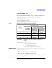
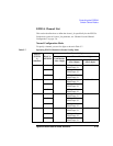
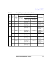
To specify a channel, you use five digits as shown in Table 5-7.
Table 5-7 Specifying E5255A Channels in Normal Config. Mode
Slot No.
(E5255A
is
installed)
Block No.
of E5255A
One Channel: 5 digits
Card Number
(first 1 digit)
Channel Number: 4 digits
Input Port No.
(next 2 digits)
Output Port No.
(last 2 digits)
1 1 1 IV Input: 01
BIAS Input: 51
01 to 08
2 IV Input: 02
BIAS Input: 52
3 IV Input: 03
BIAS Input: 53
2 1 2 IV Input: 01
BIAS Input: 51
01 to 08
2 IV Input: 02
BIAS Input: 52
3 IV Input: 03
BIAS Input: 53
3 1 3 IV Input: 01
BIAS Input: 51
01 to 08
2 IV Input: 02
BIAS Input: 52
3 IV Input: 03
BIAS Input: 53
4 1 4 IV Input: 01
BIAS Input: 51
01 to 08
2 IV Input: 02
BIAS Input: 52
3 IV Input: 03
BIAS Input: 53


