Agilent E5250A User’s Guide, Edition 9 6-31
Programming the E5250A
Using the Capacitance Compensation Routine
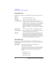
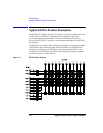
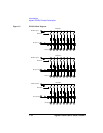
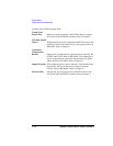
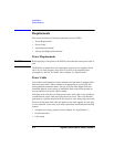
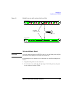
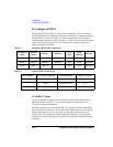
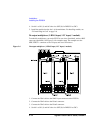
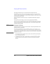
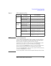
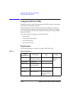
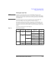
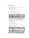
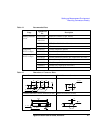
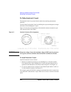
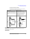
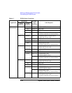
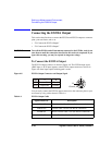
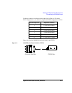
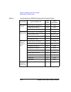
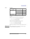
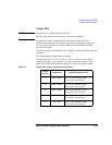
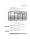
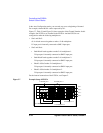
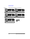
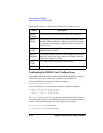
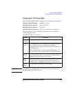
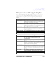
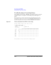
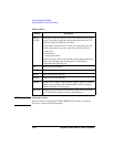
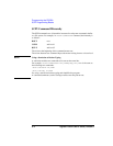
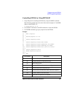
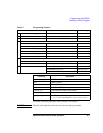
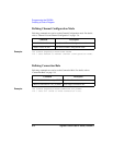
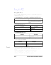
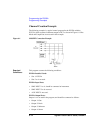
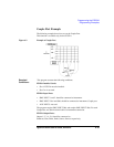
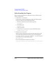
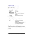
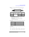
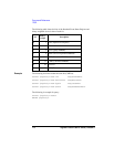
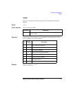
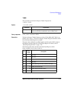
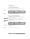
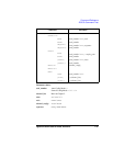
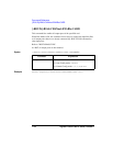
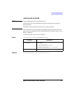
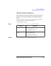
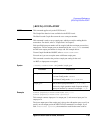
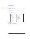
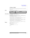
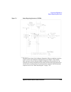
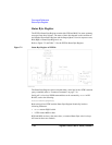
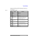
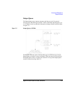
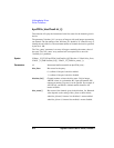
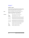
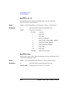
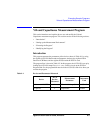
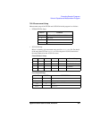
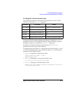
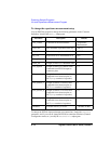
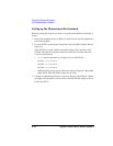
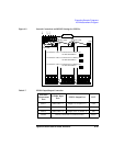
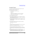
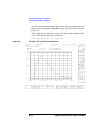
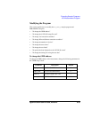
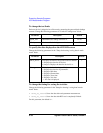
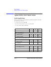
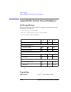
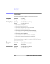
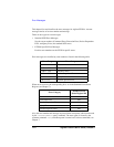
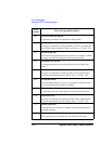
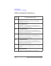
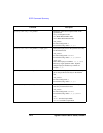
1. Measure R, L, C of your cable using the 4284A. Measurement setup is as
follows:
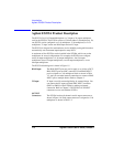
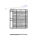
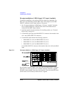
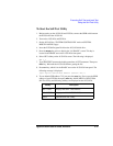
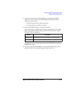
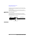
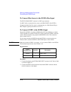
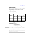
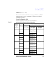
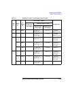
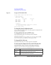
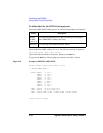
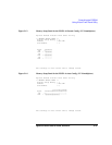
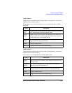
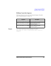
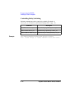
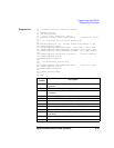
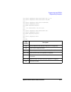
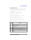
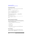
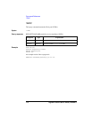
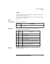
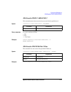
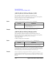
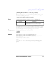
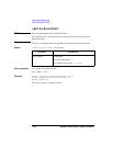
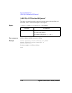
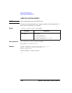
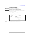
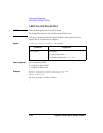
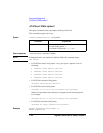
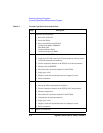
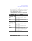
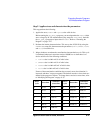
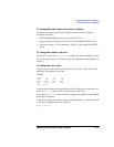
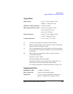
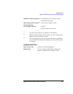
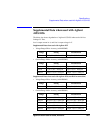
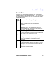
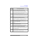
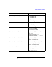
2. Overwrite the R, L, C data in the program lines listed below. The data must be in
per meter values.
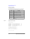
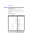
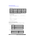
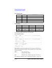
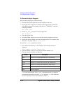
Original program defines initial data by DATA statement in the "Rlc_data" block
as shown below:
1350 Rlc_data: !
1360 ! R [ohm] L [H] C [F]
: : : :
1420 DATA 100.70E-3, 400.00E-9, 80.00E-12 !User Triax Cbl H
1430 DATA 100.70E-3, 400.00E-9, 80.00E-12 !User Triax Cbl L
1440 DATA 114.00E-3, 544.00E-9, 130.00E-12 !User Coax Cbl H
1450 DATA 114.00E-3, 544.00E-9, 130.00E-12 !User Coax Cbl L
: : : :
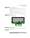
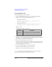
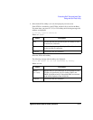
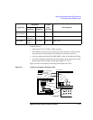
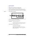
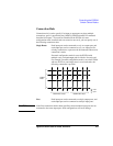
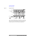
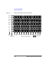
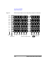
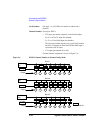
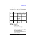
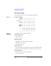
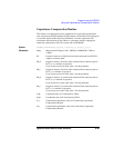
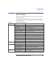
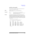
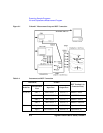
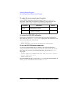
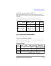
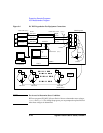
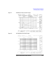
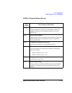
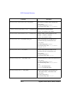
FORCE or SENSE (A)
FORCE or SENSE (B)
Insulator
Triaxial Cable
GUARD (C) GUARD (D)GROUND (F)GROUND (E)
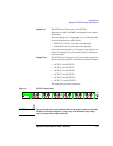
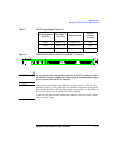
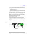
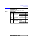
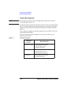
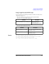
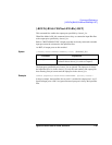
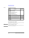
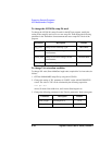
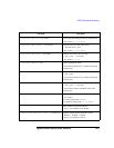
Measurement
Parameter
Measurement
Frequency
Measurement
Function
Measurement
Terminals
a
R
1 kHz to 1 MHz
b
− A and B
LSERIES
see note
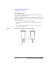
c
C PARALLEL A and C
a. See figure above.
b. Select 1 point in the frequency range.
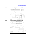
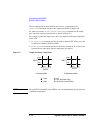
c. For triaxial cable, connect B to F directly, and measure L
between A and E.
For coaxial cable, connect B to D directly, and measure L
between A and C. Ignore E and F.
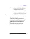
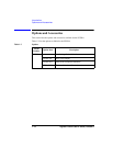
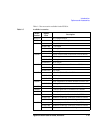
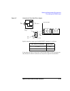
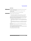
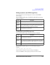
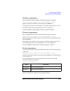
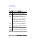
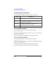
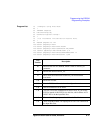
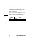
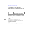
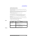
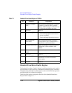
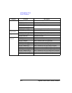
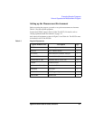
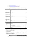
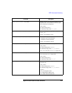
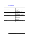
Program Line No. Defines R, L, C value of
1420 Triaxial cable for C meter High terminal
1430 Triaxial cable for C meter Low terminal
1440 Coaxial cable for C meter High terminal
1450 Coaxial cable for C meter Low terminal