


Agilent E5250A User’s Guide, Edition 9 2-11
Installation
Installing the E5250A
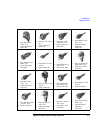
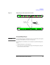
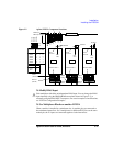
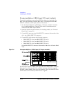
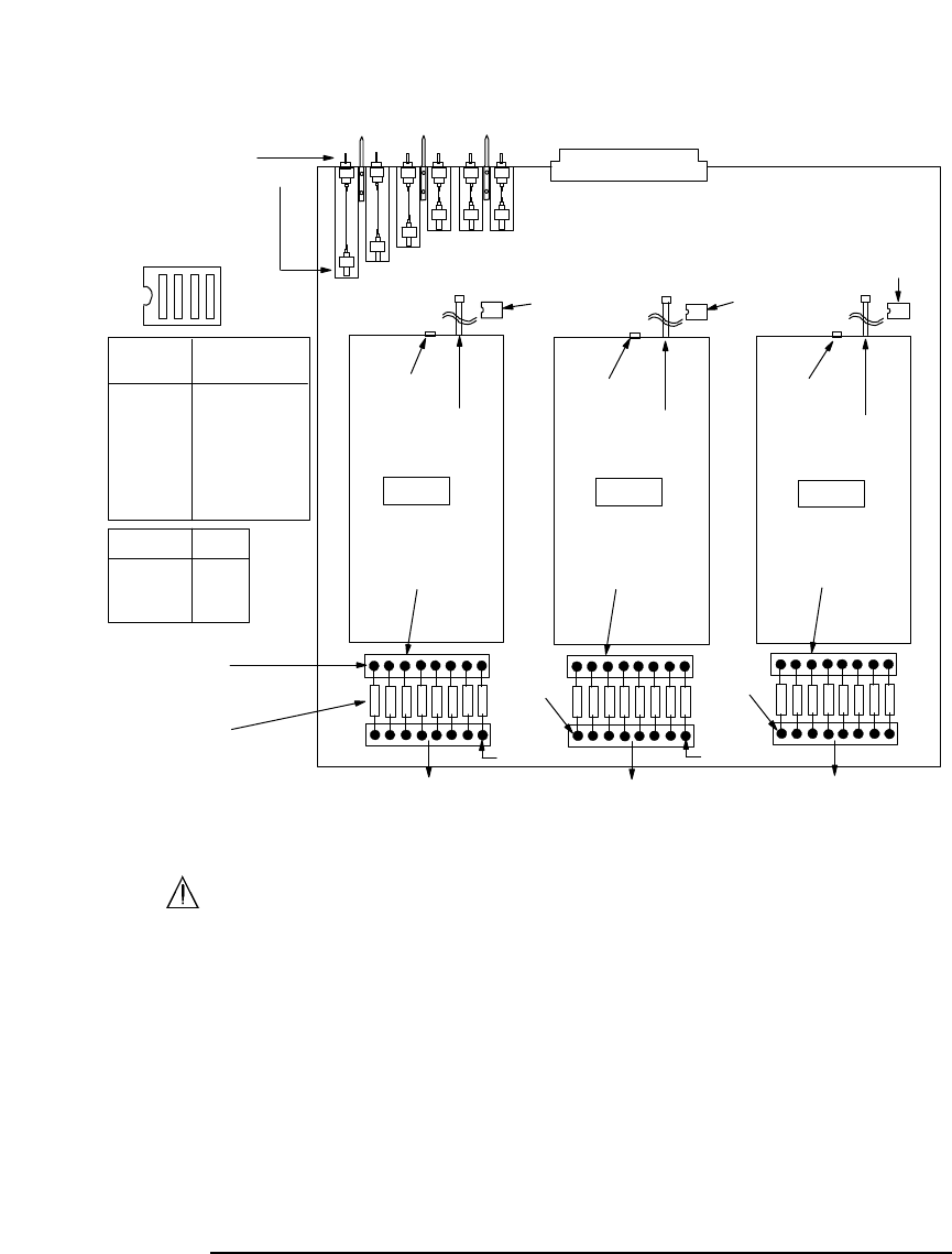
Figure 2-2 Agilent E5255A Component Locations
To Modify BIAS Input
Each multiplexer block has an independent BIAS input. You can change the BIAS
input internally using the BIASin/BIASout terminals shown in Figure 2-2, or
externally using the BIAS INPUT connectors. For actual examples of modifications,
see “E5255A Configuration Examples”.
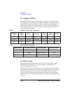
To Use Multiplexer Blocks on another E5255A
When a module is installed in a mainframe slot, six module pins are connected to
the mainframe internal bus. So, if multiplexers on different E5255As use the same
module pin, the IV inputs are connected together via the internal bus.
SMU6
SMU5
SMU4
SMU3
SMU2
SMU1
IVout3
connector
IVout2
connector
IVout1
connector
IVin1
cable
IVin3
cable
IVin2
cable
DIP SW2
DIP SW3
DIP SW1
Resistors
(Total24)
Resistor holder 1
Screws
(Total 48)
Block 1
Block3
Block 2
Resistorholder 3
Resistor holder 2
BIASin2
terminal
BIASin3
terminal
BIASout1
terminal
BIASout2
terminal
SMU input connectors
BIT1(1)
BIT3 (4)
BIT4(R)
BIT2 (2)
Resistors BIT4
0ohm 0
other 1
To BIAS INPUT 51 To BIAS INPUT 52
To BIAS INPUT 53
IVin cable DIP SW setting
connection BIT1 BIT2 BIT3
SMU1 10 0
SMU2 01 0
SMU3 11 0
SMU4 00 1
SMU5 10 1
SMU6 01 1
1: ON
0: OFF
Module pins