


9-20 Agilent E5250A User’s Guide, Edition 9
Executing Sample Programs
HCI Measurement Program
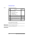
User Function Setup:
Display Setup:
Also the DATA VARIAVLES fields set Vtext and Idlin.
Auto Analysis Function:
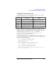
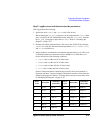
*LINE1: [ GRAD ] line on [ Y1 ] at a point where
[VG ]=[5 ]
[]
Gradient: [ 0 ]
-----------------------------------------------------------
*LINE2: [ NORMAL ] line on [ Y1 ] at a point where
[ID ]=[10u ]
[]
and a point [WHERE]
[ ID ] = [ 10u ]
-----------------------------------------------------------
*MARKER: At a point where
[ Gm ] = [ MAX(Gm) ]
[]
---------------------
*Interpolate: [ON ]
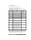
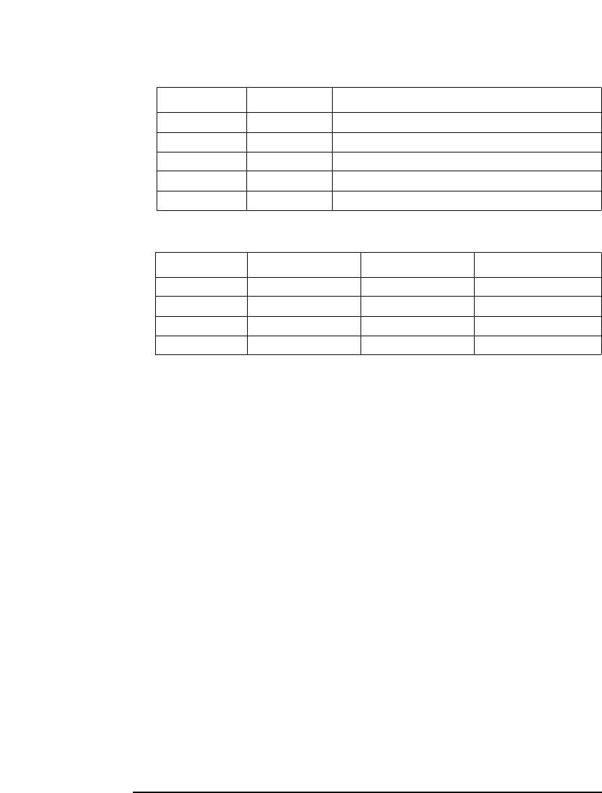
PARAM.MES setup file extracts Idlin and Vtci by using the 4155/4156 User
Function and Auto Analysis Function. These parameters are extracted with the
following conditions:
Idlin: Gate voltage VG=5 V
Substrate voltage VB=0V
Vtci: W/L Ratio (Gate width/Gate length ratio) =10 μm/1 μm
For changing the conditions, refer to “Modifying the Program” on page 9-35.
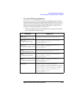
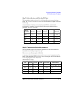
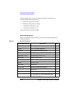
NAME UNIT DEFINITION
Gm S DIFF(ID,VG)
Vtext V @MX-(@MY1/@MY2)-AT(VD,1)/2
Gmmax S MAX(Gm)
Vtci V @L2X
Idlin A @L1Y1
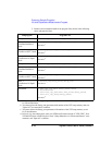
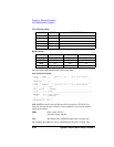
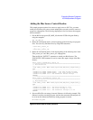
Xaxis Y1axis Y2axis
NAME VG ID Gm
SCALE LINEAR LINEAR LINEAR
MIN 0 V 0 A 0 S
MAX 5 V 2 mA 1.5 mS