Agilent E5250A User’s Guide, Edition 9 9-7
Executing Sample Programs
Vth and Capacitance Measurement Program
Setting up the Measurement Environment
Before executing the program, you need to set up the measurement environment.
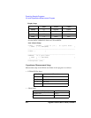
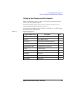
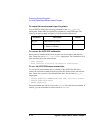
Table 9-3 lists the required equipment.
Connect the E5250A output to Device Under Test (DUT). For details, refer to
“Setting up Measurement Environment” on page 4-1.
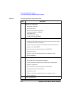
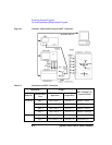
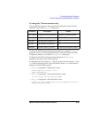
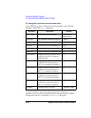
And connect all equipment as shown in Figure 9-1 and Table 9-4. The E5252A must
be installed in slot1 of the E5250A.
Table 9-3 Required Equipments
Agilent Model/Part No. Description Qty.
E5250A Low Leakage Switch Mainframe 1
E5252A 10×12 Matrix Switch 1
4155/4156 Semiconductor Parameter Analyzer 1
16494A-003 Triaxial Cable (80 cm) 4
16494A-001 or -002 Triaxial Cable (1.5 m or 3 m) 6
16495F Connector Plate 1
4284A with 4284A-006 Precision LCR Meter 1
16048D/E Test Lead 1
1250-2405 BNC T-type Adapter 2
10833A/B/C GPIB Cable 3


