


5-22 Agilent E5250A User’s Guide, Edition 9
Controlling the E5250A
Switch Control Basics
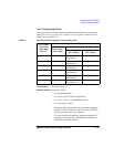
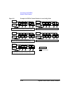
In the Auto Configuration mode, you can omit any zeros at beginning of channel.
For example, channel 00101 can be expressed by 101.
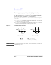
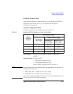
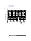
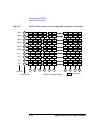
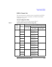
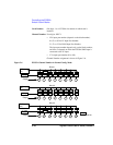
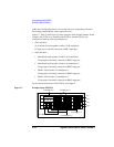
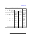
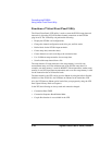
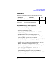
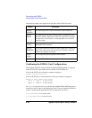
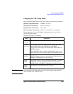
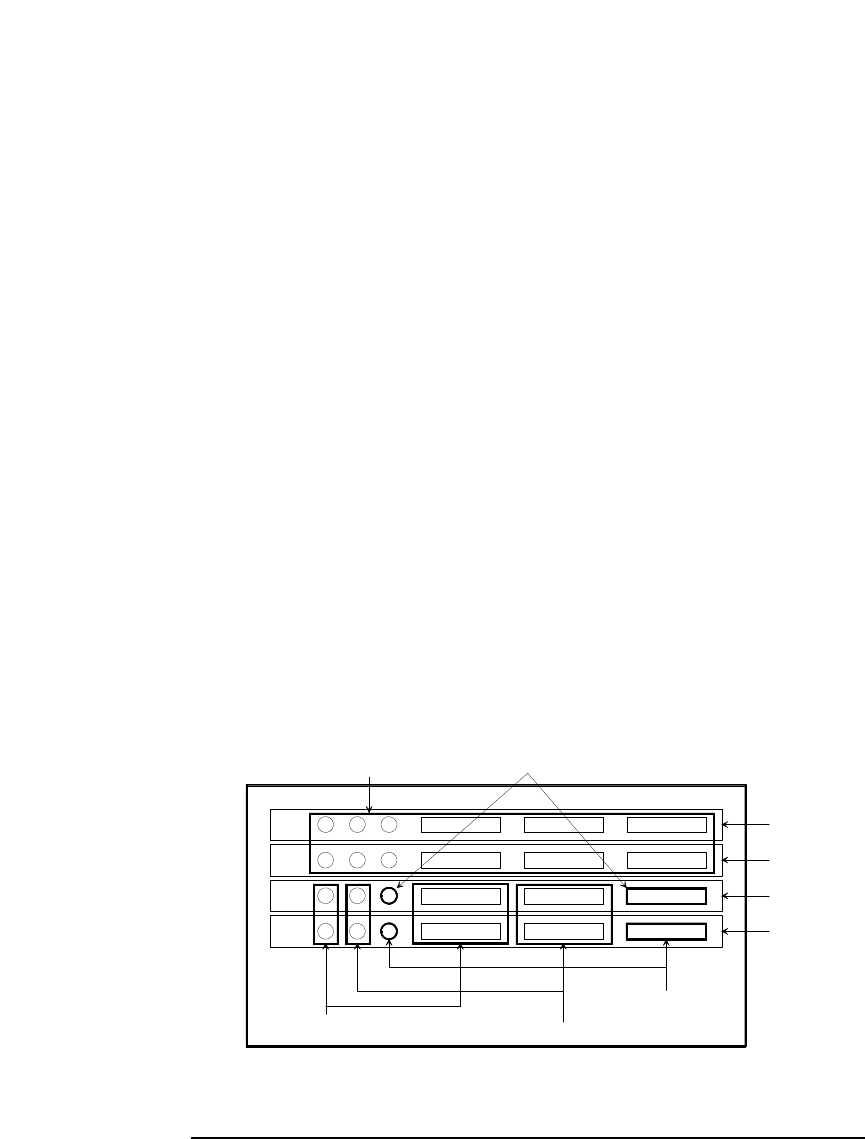
Figure 5-7, Table 5-9 and Figure 5-8 show examples of the Channel Number. In this
example, four E5255As are installed in the E5250A. And the E5255As are
configured to make the following multiplexers:
• Slot1 and Slot2:
all six blocks are used together to make a 2×48 multiplexer.
IV input port is internally connected to SMU1 input port.
• Slot3 and Slot4:
• Both Block1 used together to make 2×16 multiplexer-1.
IV input port is internally connected to SMU2 input port.
• Both Block2 used together to make 2×16 multiplexer-2.
IV input port is internally connected to SMU3 input port.
• Block3 of Slot3 makes 2×8 multiplexer-1.
IV input port is internally connected to SMU4 input port.
• Block3 of Slot4 makes 2×8 multiplexer-2.
IV input port is internally connected to SMU5 input port.
For the internal connections of the E5255A, see Chapter 2.
Figure 5-7 Example Setup of E5255A
2x48 Multiplexer
slot 2
slot 3
slot 4
slot 1
2x16 Multiplexer-1
2x8 Multiplexer-1
2x8 Multiplexer-2
2x16 Multiplexer-2