Chapter 12: AI2524 X.25 Configuration Steps
August 1997 Page 12-7
2524UM
maximum packet sizes. PVCs also use these default values unless dif-
ferent values are configured.
In interface configuration mode, set the default input and output max-
imum packet sizes:
1. Set the default input maximum packet size.
x25 ips
bytes
2. Set the default output maximum packet size.
x25 ops
bytes
To send a packet larger than the agreed on X.25 packet size over an
X.25 virtual circuit, the Cisco IOS software must break the packet into
two or more X.25 packets with the M-bit (More data bit) set. The re-
ceiving device collects all packets in the M-bit sequence and reassem-
bles them into the original packet.
It is possible to define default packet sizes that cannot be supported by
the lower layer (see the LAPB N1 parameter). However, the router will
negotiate lower maximum packet sizes for all SVCs so the agreed on
sizes can be carried. The Cisco IOS software will also refuse a PVC
configuration if the resulting maximum packet sizes cannot be sup-
ported by the lower layer.
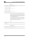
Example: Typical X.25 Configuration
This example shows the complete configuration for a serial interface
connected to a commercial X.25 PDN for routing the IP protocol. The
IP subnetwork address 172.25.9.0 has been assigned for the X.25 net-
work.
Note: When you are routing IP over X.25, you must treat the
X.25 network as a single IP network or subnetwork. Map
entries for routers with addresses on subnetworks other
than the one on which the interface's IP address is stored
are ignored by the routing software. All routers using the
subnet number must have map entries for all others
routers. Using the broadcast option with dynamic routing
can result in larger traffic loads, requiring a larger hold
queue, larger window sizes, or multiple virtual circuits.


