AI2524 Router Card User’s Manual
Page 13-30 August 1997
2524UM
Example: PVC Switching Configuration
You can configure your router as a dedicated, DCE-only Frame Relay
switch. Switching is based on DLCIs. The incoming DLCI is exam-
ined, and the outgoing interface and DLCI are determined. Switching
takes place when the incoming DLCI in the packet is replaced by the
outgoing DLCI, and the packet is sent out the outgoing interface.
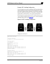
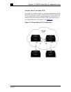
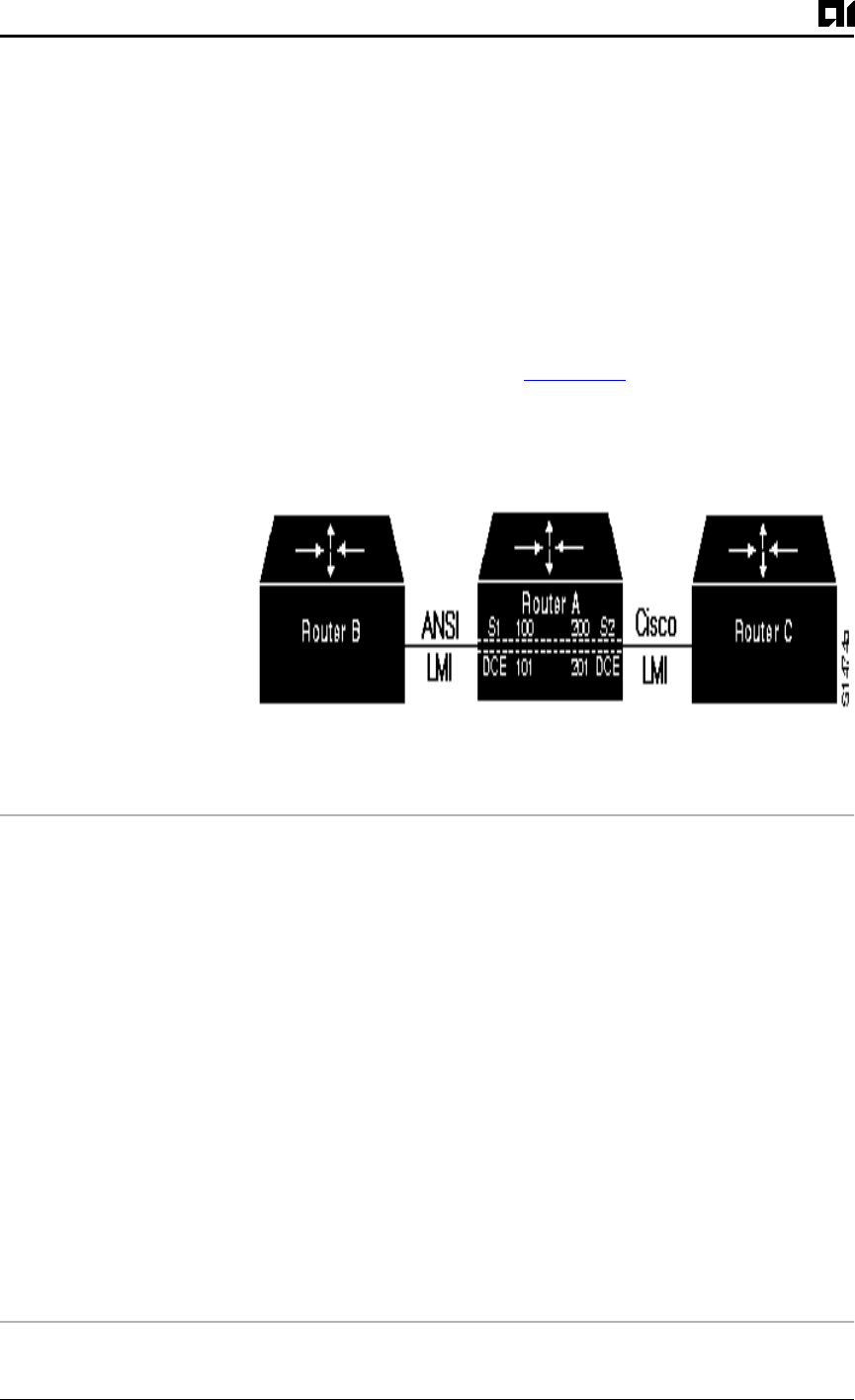
In this example, the router switches two PVCs between interface serial
1 and 2. Frames with DLCI 100 received on serial 1 will be transmitted
with DLCI 200 on serial 2 (see Figure 13-4
).
Figure 13-4:PVC Switching Configuration
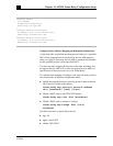
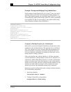
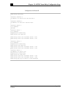
Configuration for Router A
frame-relay switching
!
interface Ethernet0
ip address 131.108.160.58 255.255.255.0
!
interface Serial1
no ip address
encapsulation frame-relay
keepalive 15
frame-relay lmi-type ansi
frame-relay intf-type dce
frame-relay route 100 interface Serial2 200
frame-relay route 101 interface Serial2 201
clockrate 2000000
!
interface Serial2
encapsulation frame-relay keepalive 15
frame-relay intf-type dce
frame-relay route 200 interface Serial1 100
frame-relay route 201 interface Serial1 101
clockrate 64000


