Chapter 13: AI2524 Frame Relay Configuration Steps
August 1997 Page 13-29
2524UM
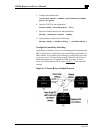
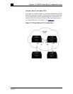
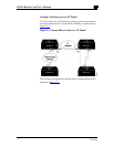
In Figure 13-3, Routers A, B, and C are Frame Relay DTEs connected
to each other via a Frame Relay network. Our implementation of
Frame Relay switching allows our devices to be used as depicted in
this Frame Relay network.
Perform the tasks in these sections, as necessary, to configure Frame
Relay switching:
z
Enable Frame Relay Switching
z
Configure a Frame Relay DTE Device, DCE Switch, or NNI Sup-
port
z
Specify the Static Rout
Enable Frame Relay Switching
In global configuration mode, enable packet switching before config-
uring it on a Frame Relay DTE or DCE or with Network-to-Network
Interface (NNI) support:
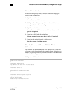
frame-relay switching
Configure a Frame Relay DTE Device, DCE Switch, or NNI
Support
In interface configuration mode, configure an interface as a DTE de-
vice or a DCE switch or as a switch connected to a switch to support
NNI connections:
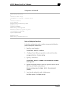
frame-relay intf-type [dce | dte | nni]
DCE is the default.
Specify the Static Route
In interface configuration mode, specify a static route for PVC switch-
ing:
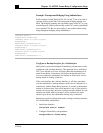
frame-relay route in-dlci out-interface
out-dlci


