


Chapter 8: Virtual LANs and GVRP
110 Section I: Using the Menus Interface
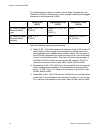
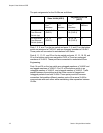
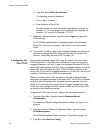
The table below lists the port numbers for the Sales, Engineering, and
Production VLANs on the switches. In this example, all ports are untagged
members of their respective VLANS.
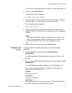
Note the following concerning the example:
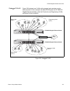
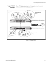
Sales VLAN - This VLAN spans both switches. It has a VID value of 2
and consists of four untagged port members on the top switch and
three untagged port members on the bottom switch. The two parts of
the VLAN are connected by a direct link from port 4 on the top switch
to port 1 on the bottom switch. This direct link allows the two parts of
the Sales VLAN to function as one logical LAN segment. Port 20 is
used as a connection to the router, other VLANs, and the WAN.
Engineering VLAN - This VLAN is on the top switch only and consists
of four untagged port members. The workstations are connected to
ports 3, 5, and 7. Port 24 is used as a connection to the router, other
VLANs, and the WAN.
Production VLAN - This VLAN has the VLAN of 4 and is on the bottom
switch only. The workstations are connected to ports 3, 6, and 8. Port
21 is used as a connection to the router, other VLANS, and the WAN.
Sales VLAN
(VID 2)
Engineering VLAN
(VID 3)
Production VLAN
(VID 4)
AT-9000/24 Gigabit
Ethernet Switch
(top)
Ports 1, 3-5, 7, 20
(PVID 2)
Ports 9, 11, 13, 21, 23
& 24
(PVID 3)
None
AT-9000/24 Gigabit
Ethernet Switch
(bottom)
Ports 1, 2, 4
(PVID 2)
None Ports 10, 12, 18, 20-
24 (PVID 4)