


Chapter 8: Virtual LANs and GVRP
112 Section I: Using the Menus Interface
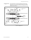
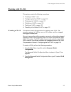
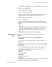
The port assignments for the VLANs are as follows:
Ports 1, 2, 5, and 7 on the top switch and ports 2, 4, and 13 on the bottom
switch are assigned a PVID of 2 and are untagged members of VLAN 2.
These ports are connected to workstations from Sales.
Ports 9, 11, 13, 21, and 23 on the top switch and ports 10, 12, 18, 20, and
22 on the bottom switch are assigned a PVID of 3 and are untagged
members of VLAN 3. These ports are connected to workstations from
Engineering.
Ports 14 and 24 on the top switch are untagged members of VLAN2 and
are tagged members of VLAN 3. Port 13 on the bottom switch is an
untagged member of VLAN 2, and a tagged member of VLAN 3. Traffic
passed between the switches and the router consist of tagged and
untagged packets from both VLANs. These ports provide a common
connection that enables different member ports of the same VLAN to
communicate with each other while maintaining data separation between
VLANs.
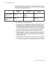
Sales VLAN (VID 2)
Engineering VLAN
(VID 3)
Untagged
Port
Members
Tagged
Port
Members
Untagged
Port
Members
Tagged Port
Members
AT-8000/8POE
Fast Ethernet
Switch (top)
1, 2, 5, 7, 24
(PVID 2)
None 9, 11, 13, 21,
23 (PVID 3)
14, 24
AT-8000/8POE
Fast Ethernet
Switch (bottom)
2, 4, 13
(PVID 2)
None 10, 12, 18,
22 (PVID 3)
13