


Chapter 11: Rapid Spanning Tree Protocol (RSTP)
164 Section II: Menus Interface
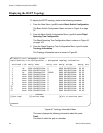
Displaying the RSTP Topology
To display the RSTP topology, perform the following procedure:
1. From the Main Menu, type B to select Basic Switch Configuration.
The Basic Switch Configuration Menu is shown in Figure 4 on page
32.
2. From the Basic Switch Configuration Menu, type S to select Rapid
Spanning Tree Configuration.
The Rapid Spanning Tree Configuration Menu is shown in Figure 42
on page 153.
3. From the Rapid Spanning Tree Configuration Menu, type I to select
Topology Information.
The Topology Information menu is shown in Figure 43.
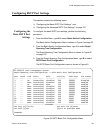
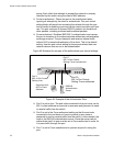
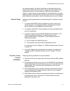
Figure 45. Topology Information Menu
This menu displays the following information about the ports:
Trunk
The trunk of which the port is a member.
AT-9000/24 Local Management System
Rapid Spanning Tree Configuration -> Designated Topology Information
PortTrunk Link Desig. Root Desig. Cost Desig. Bridge Desig. Port
--------- ---- ----------------- ----------- ----------------- -----------
1 Up 8000 00c08f1211bb 0 8000 00c08f1211bb 00 00
2 Down 8000 00c08f1211bb 0 8000 00c08f1211bb 00 00
3 Up 8000 000c46aa7fal 200000 8000 003084000000 00 03
4 Down 8000 00c08f1211bb 0 8000 00c08f1211bb 00 00
5 Down 8000 00c08f1211bb 0 8000 00c08f1211bb 00 00
6 Down 8000 00c08f1211bb 0 8000 00c08f1211bb 00 00
7 Down 8000 00c08f1211bb 0 8000 00c08f1211bb 00 00
8 Down 8000 00c08f1211bb 0 8000 00c08f1211bb 00 00
9 Down 8000 00c08f1211bb 0 8000 00c08f1211bb 00 00
10 Down 8000 00c08f1211bb 0 8000 00c08f1211bb 00 00
11 Down 8000 00c08f1211bb 0 8000 00c08f1211bb 00 00
12 Down 8000 00c08f1211bb 0 8000 00c08f1211bb 00 00
----------------------- <COMMAND> -------------------------------------------
[N]ext Page [P]revious Page [Q]uit to previous menu
Command>