


Chapter 25: RSTP
278 Section II: Web Browser Interface
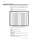
Viewing the RSTP Topology
To view the current RSTP topology, perform the following procedure:
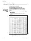
1. From the Basic Config menu, select Rapid Spanning Tree > RSTP
Topology.
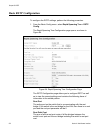
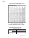
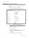
The Designated Topology Information page opens, as shown in
Figure 87.
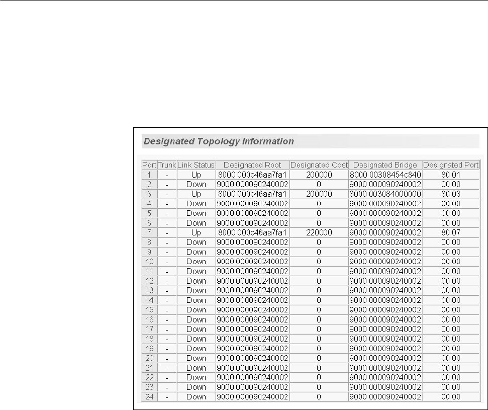
Figure 87. Designated Topology Information Page
This page displays the following information about the ports:
Trunk
The trunk of which the port is a member.
Link Status
Whether the link on the port is up or down.
Designated Root
The designated root bridge to which the switch’s root port is actively
connected.
Designated Cost
The sum of all the root port costs on all bridges, including the switch,
between the switch and the root bridge.