Preparing the Phone System 3-1
Octel 200/300 S.4.1PB60019−01
3.1 HOW THE OCTEL 200/300 WORKS WITH THE PHONE
SYSTEM
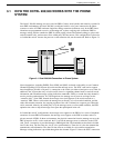
The OctelR 200/300 message servers work with PBXs, Centrex, most hybrids, and some key systems. In
most PBX environments, the Octel 200/300 is configured with its voice ports connected to the phone
system as a series of DTMF touchtone single line analog extensions (touchtone sets). In the PBX, these
extensions are programmed to receive an incoming call, to place outgoing calls (within the PBX for
message waiting and also outside the PBX for offsite paging, alarm calls and networking), to place calls
on hold, transfer calls, and reconnect if the called party does not answer. This configuration is referred to
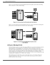
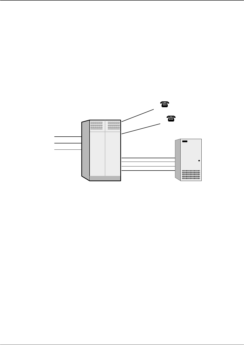
as “behind the switch” because the ports are on the extension side, not the trunk side. Refer to Figure 3-1.
Trunks
Extensions to Ports
Extensions
PBX
Octel
200/300
Figure 3-1 Octel 200/300 Connection to Phone System
Newer integrations, including DNPSS, Euro−ISDN, and QSIG, are based on the ability to use Common
Channel Signalling (CCS) between the switch and the message server. The DTIC card used to support
these integrations provides a 30-port E−1 connection to the switch via either twisted pair or coax cable. In
addition to the 30 ports that carry voice/fax traffic, there is a signalling channel used to send call record
information and to handle message waiting indication commands. Finally, a second data-only channel is
used to provide synchronization. In CCS integrations, the message server ports are no longer on the
“extension side”’ of the PBX. Instead, the message server itself appears to the switch network as a
“transient” PBX. When a call reaches the message server directly or in a forwarded condition, and the
caller dials another extension, the outgoing segment of the call is initiated on a separate port. When the
call is answered, either by the called party or by the message server on a forwarded condition, the PBX
optimizes the route to drop all message server ports that participated in the call.
In “behind the switch” configurations, the message server appears to the PBX to be a series of telephone
extensions. In some PBX environments, the message server appears to the PBX as another node in a
private network of PBXs. In these environments, the physical connection from the message server to the
PBX is based on an E-1 card at each end. the E-1 card in the message server is referred to as the DTIC
card. The E-1 connection is provided through a 2MB digital link. The bandwidth on that link is divided
into 32 time slots. The first time slot, slot 0, is for synchronization. Time slot 16 is the data channel that
transmits the call information. The other 30 time slots are available for voice and fax transmission.
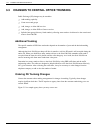
Message waiting indication is provided through the data channel. Figure 3-2 shows the DTIC connection.


