9-60 Installation and Maintenance Volume
Octel 200/300 S.4.1 PB60019−01
Caution!
The Octel 300 is sensitive to static electricity. Do not
attempt the following procedures without wearing an
antistatic wrist strap.
Removing the Octel 300 Load Resistor Assembly
Use the following procedures to remove the load resistor assembly:
1. Unlock and open the door of the cabinet.
2. Put on an antistatic wrist strap. Connect it to an unpainted portion of the cabinet.
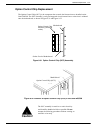
3. Turn OFF the PSU. Refer to the Power Supply Unit Replacement section in this chapter for details
about turning OFF the power to the message server.
4. Use a flat-blade screwdriver to loosen the two captive screws on the front of the fan assembly.
5. Pull the fan assembly forward about 25mm (1 inch). The fan assembly does not need to be removed
from the cabinet.
6. At the rear of the cabinet, remove the four screws that hold the bottom panel to the back of the
cabinet, and set the panel aside.
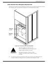
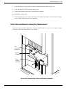
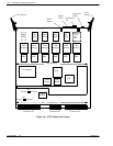
7. Locate the load resistor assembly on the shelf B backplane (refer to Figure 9-30). Note that the
harness attached to the load resistor assembly is also attached to the shelf B disk drive backplane and
to the fan assembly.
8. Remove the three screws that secure the fan-assembly connector to the cabinet.
9. Disconnect the harness where it plugs into the shelf B backplane.
10. Remove four screws and washers that secure the load resistor assembly sheet metal to the cabinet,
and set the load resistor assembly aside.
Installing the Octel 300 Load Resistor Assembly
Use the following procedures to install a load resistor assembly:
1. Put on an antistatic wrist strap. Connect it to an unpainted portion of the cabinet.
2. Verify that the power supply switch is OFF.
3. Secure the load resistor assembly sheet metal to the chassis with the four screws and washers, as
shown in Figure 9-30.
4. Connect the load resistor assembly/fan-assembly harness to the shelf B backplane.
5. Secure the fan assembly connector to the cabinet with three screws.
6. Attach the bottom rear panel to the cabinet with four screws.
7. Slide the fan assembly back into the cabinet, and secure it with the captive screws on the front of the
assembly.
8. Turn ON the message server and check for correct message server operation. Make sure that the fans
are spinning.
9. Close and lock the door of the cabinet.


