4−26 Installation and Maintenance Volume
Octel 200/300 S.4.1 PB60019−01
4.6 CONNECTING THE PHONE SYSTEM
TO THE OCTEL 200/300
After you have verified that both the message server and the PBX are configured correctly, you must
connect the Octel 200/300 to the PBX.
Connection Overview
The Octel 200/300 installation involves connecting 25-pair cables from the rear of the Octel 200/300 to a
66M4-4W connector block, which is mounted on a backboard. Each 25-pair cable supports one slot on
the Octel 200/300. The Octel 200/300 is then connected with jumper wire to the PBX.
. Please refer to the Pin Assignment for Message Server Cards and Ports section in this chapter for
specific message server and port pin assignments.
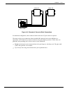
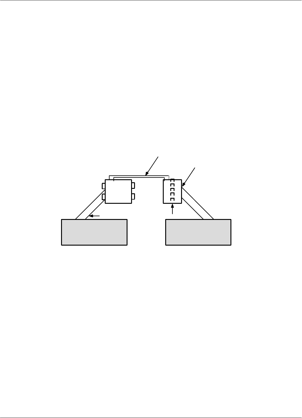
It is recommended that the PBX extensions to be associated with the Octel 200/300 be terminated on a
66M connector block, or equivalent, for ease of installation and fault isolation, as shown in Figure 4-8.
Figure 4-8 Typical Octel 200/300 Connections
66M4-4W 66M
Cross-connect wire
––––––
––––––
––––––
––––––
––––––
––––
––––
––––
––––
––––
Bridge clips25-pair cable
PBX extensions
terminate here
PBX
Octel 200/300
Verifying the Equipment
The following equipment is required for installation of the Octel 200/300:
- PBX extensions associated with the Octel 200/300, to be terminated on a 66M connector block, or
equivalent
- Octel 200/300 installation kit
. If you need to install a DAC card, refer to the Direct Access Card Installation and Maintenance
Manual, part number PB10105−02.
Each line card installation kit, Part No. 740-6034-001, installs four line-card slots. To determine the
number of line-card installation kits to order, divide the total number of line-card slots by four. The kit
contains the following:
- One 66M4-4W connector block, Part No. PJ86001-01
- Four 10-foot cables with male-to-female 25-pair connectors, Part No. SA10079-02
- Two self-tap 10 x 5/8 PH sheet-metal screws, Part No. HH53024-01


