9-58 Installation and Maintenance Volume
Octel 200/300 S.4.1 PB60019−01
Removing the Octel 300 Disk Drive Backplane
Use the following procedure to remove a new disk drive backplane:
1. Unlock and open the door of the cabinet.
2. Put on an antistatic wrist strap. Connect it to an unpainted portion of the cabinet.
3. Turn OFF the PSU. Refer to the Power Supply Unit Replacement section in this chapter for details
about turning OFF the power to the message server.
4. Use a flat-blade screwdriver to loosen the two captive screws on the front of each of the disk drive
assemblies on the shelf that has the faulty backplane. Disengage each disk drive assembly from the
backplane; the disk drive assembly should stay in the cabinet.
5. At the rear of the Octel 300 cabinet, disconnect all cables attached to the motherboard. Mark the
cables so that they can be reattached at the same positions.
6. Disconnect the power cord from the cabinet.
7. Remove the four screws that secure the bottom panel to the cabinet and slowly remove the panel.
Cables that were disconnected from the motherboard in step 5 might be fastened to the bottom panel
with cable ties. These cables can remain fastened.
8. Disconnect all harnesses and cables from the backplane being replaced. Make sure that the ends of
the harnesses and cables not directly attached to the backplane being replaced remain connected.
9. If the shelf B disk drive backplane is being removed, and the message server is equipped with a load
resistor assembly, remove the four screws and washers that secure the load resistor assembly to the
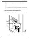
message server. Refer to Figure 9-30 to verify whether a load resistor assembly is present.
10. Remove the screws along the top and bottom edges of the backplane and remove it.
Installing the Octel 300 Disk Drive Backplane
Use the following procedure to install a new disk drive backplane:
Caution!
The backplane must be aligned precisely to ensure
that the disk drive assembly is fully engaged with the
backplane. To accomplish this, follow the
instructions exactly.
1. Hold the new backplane up to the cabinet and install a screw in the top, center screw hole to hold it
in place.
2. If the shelf B backplane is being installed in a message server with a load resistor assembly, secure
the load resistor assembly to the cabinet with four screws and washers, as shown in Figure 9-30. Do
not tighten the screws.
3. Install all of the screws along the top and bottom edges of the backplane so that the backplane is
barely able to move, with only a small gap between the screwheads and the backplane.
4. At the front of the cabinet, push each disk drive assembly into its mating connector on the backplane.
5. Tighten all the screws on the top and bottom edges of the backplane.
6. Reconnect all harnesses and cables to the backplane.


