4−54 Installation and Maintenance Volume
Octel 200/300 S.4.1 PB60019−01
External Alarm Port
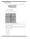
The external alarm port uses a 9-pin DB9 female connector with the following pin arrangement:
15
69
S
S
S
S
S
S
S
S
S
Front View DB9 Male Connector
- Use connector J3 for the Octel 200.
- Use connector J5 for the Octel 300.
The external-alarm connector pin assignments are as follows:
AJ1 and AJ2 Connector Pin Assignments
Pin Number
Signal Function
1 Relay A, Pin 1
2 Relay B, Pin 1
3 LINK
4 GND
5 GND
6 Relay A, Pin 2
7 Relay B, Pin 2
8 LINK
9 GND
Relay A is the major alarm relay. Relay B is the minor alarm relay. A relay is open when there is no
alarm. When a relay is closed, it indicates an alarm condition.
With power removed from the cabinet, both Relay A and Relay B are in the closed position (normally
closed), indicating an alarm condition.
Pins 3 and 8 are linked together to provide a loop. You can use this as a confirmation that an alarm cable
is installed. Pins 4, 5, and 9 are connected to cabinet ground. These pins can be jumpered to a relay
contact, if closure to ground is required.
Both Relay A and Relay B are rated at
- 48 Vdc maximum
- 0.5 A maximum
The link loop is rated at
- 12 Vdc maximum
- 200 mA maximum


