


Installation 4−15
PB60019−01 Octel 200/300 S.4.1
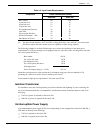
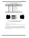
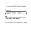
Table 4-4 DCE Pinouts for Cable Connections Between the RS-232C
Terminal and the Octel 200/300
Pin EIA/CKT Signal Function
1
2
3
4
5
7
8
20
AA
BA
BB
CA
CB
AB
CF
CD
Protective ground
Transmit data (TX)
Receive data (RX)
Request to send (RTS)
Clear to send (CTS)
Signal ground
Receive-line signal detector (DCD)
Data terminal ready (DTR)
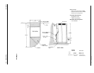
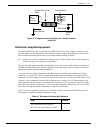
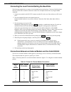
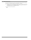
Figure 4-6 First and Second RS-232C Serial-Port Cable Pinouts
for Connection to Terminal Equipment (DTE)
1
2
3
4
5
7
8
20
1 Protection Ground
2TX
3RX
4RTS
5 CTS
7 Signal Ground
8 DCD
20 DTR
Octel 200/300 (DCE)
To Terminal (DTE)
For correct operation:
- DTR (pin 20) must be asserted TRUE by the terminal.
- RTS (pin 4) must be asserted TRUE by the terminal when the terminal is able to accept data, or pin 4
must be left open.
If the terminal/teleprinter equipment has pins 1 and 7 connected together, intermittent problems with
the Octel 200/300 might occur. Terminal/teleprinters requiring Data Set Ready (DSR) could require that
pins 6 and 8 be connected together, or pins 8 and 20 be connected together at the terminal end of the
RS-232C cable. If you have a problem with or question about your terminal/teleprinter, contact technical
support resources.call Ericsson.