


7-14
Network Processing Engine and Network Services Engine Installation and Configuration
OL-4448-12
Chapter 7 NPE-G1 and NPE-G2 Installation and Configuration Information
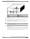
Removing the Network Processing Engine
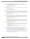
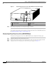
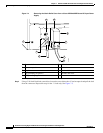
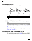
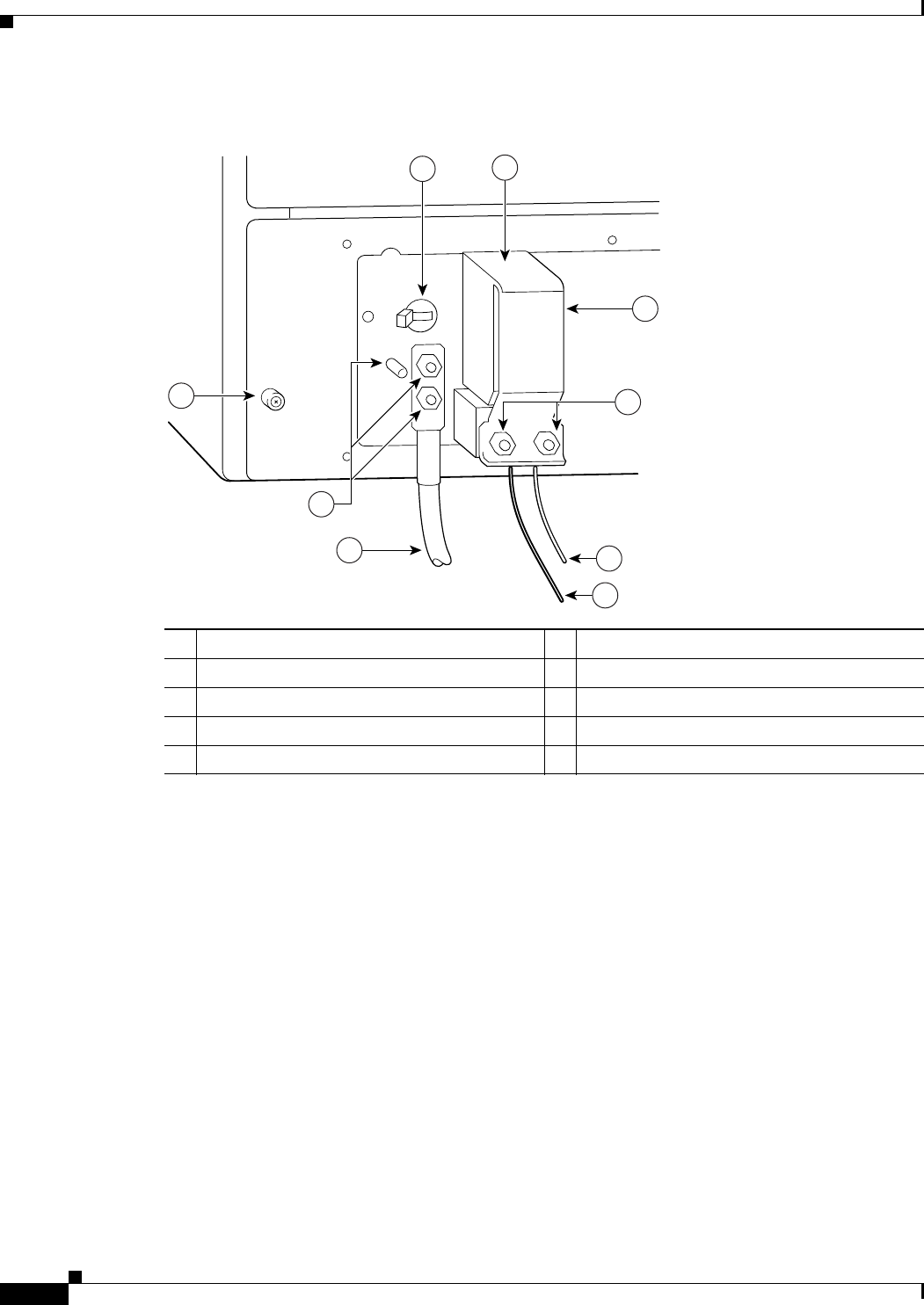
Figure 7-4 Removing the Strain-Relief Cover from a Cisco uBR7246VXR Router DC-Input Power
Supply
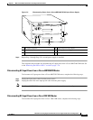
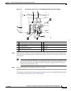
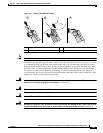
Step 4 Using a 3/16-inch flat-blade screwdriver, loosen the screw below the +V lead receptacle and pull the lead
from the connector. Repeat this step for the –V lead only. See
Figure 7-5.
1 Power switch 6 –V lead
2 Power receptacle 7 +V lead
3 Captive screw 8 Strain-relief cover
4 M5 grounding receptacles 9 M4 nuts and studs
5 M5 grounding lug
66408
3
5
7
6
8
1
2
9
4