


9-32
Network Processing Engine and Network Services Engine Installation and Configuration
OL-4448-12
Chapter 9 Removing and Installing the NPE or NSE
Removing and Replacing the NPE or NSE
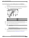
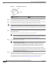
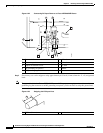
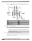
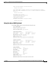
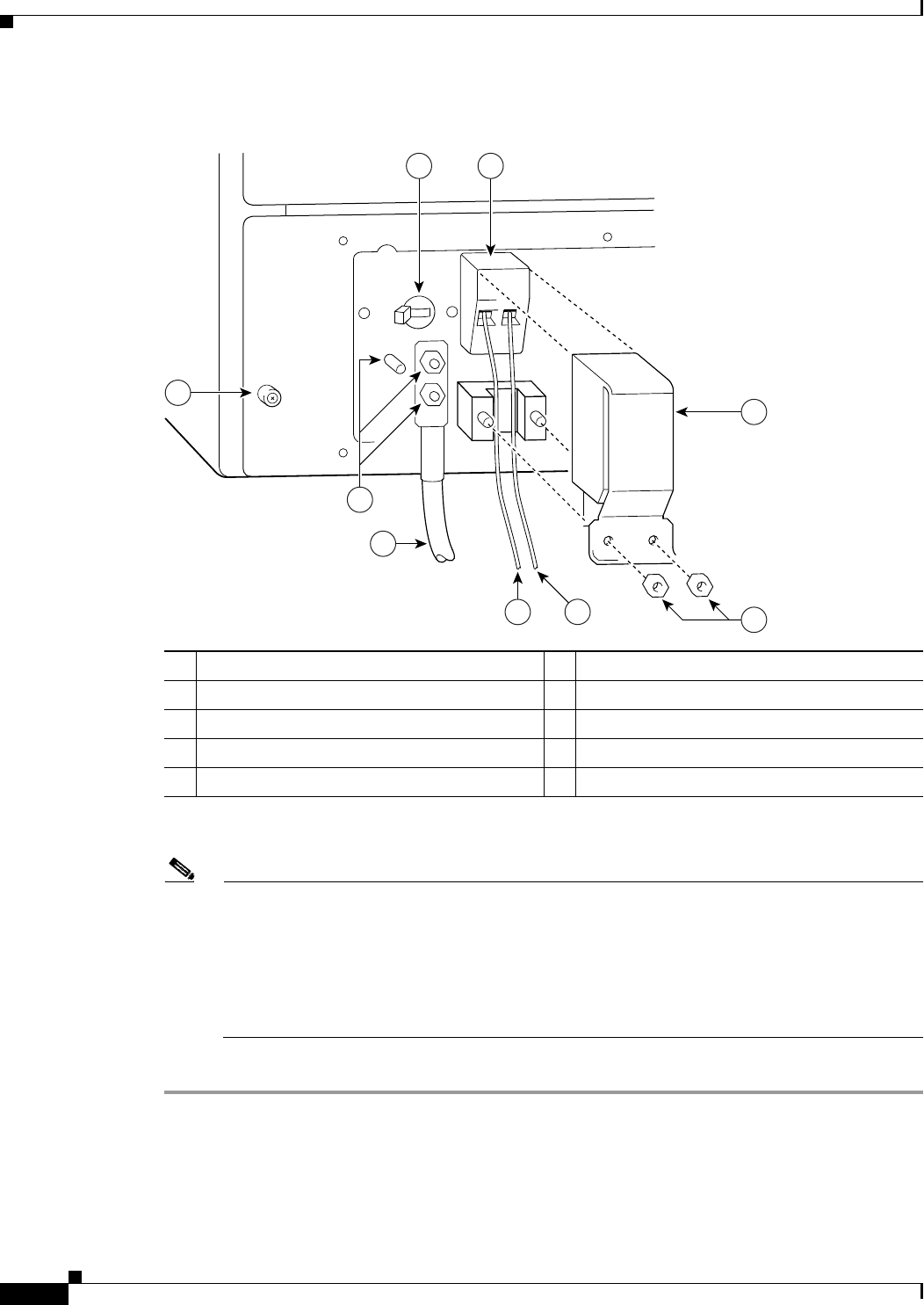
Figure 9-24 Replacing the Strain-Relief Cover on a Cisco uBR7246VXR Router DC-Input Power
Supply
Step 9 Restore current to the –V and +V leads.
Note For the Cisco uBR7246VXR router, each DC-input power supply rating is 14A, 700 volt ampere
(VA).
This product relies on the building’s installation for short-circuit (overcurrent) protection.
Ensure that a listed and certified fuse or circuit breaker, 35A minimum 60 VDC, is used on all
current-carrying conductors. Site wiring and circuit breakers need to be sized to accommodate
the maximum values for safety reasons.
Step 10 Repeat Step 1 through Step 9 if a second power supply is installed.
This completes the steps for reconnecting DC-input power to a Cisco uBR7246VXR router. Proceed to
the following section, “
Powering Up the Router.”
1 Power switch 6 –V lead
2 Power receptacle 7 +V lead
3 Captive installation screw 8 Strain-relief cover
4 M5 grounding receptacles 9 M4 nuts
5 M5 grounding lug
3
5
6
7
8
1
2
9
4
66409