


7-40
Network Processing Engine and Network Services Engine Installation and Configuration
OL-4448-12
Chapter 7 NPE-G1 and NPE-G2 Installation and Configuration Information
Installing the NPE-G1 or NPE-G2
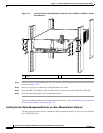
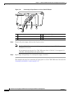
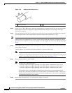
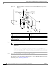
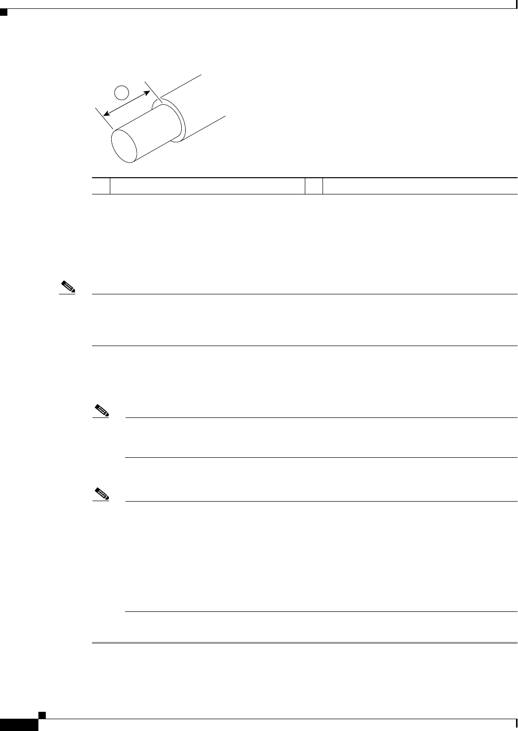
Figure 7-28 Stripping the DC-Input Lines
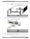
Step 4 For the Cisco 7200 VXR routers, insert the stripped end of the ground lead all the way into the ground
lead receptacle on the DC-input power supply and tighten the receptacle screw using a 3/16-inch
flat-blade screwdriver.
Step 5 Insert the stripped end of the +V lead all the way into the +V lead receptacle and tighten the receptacle
screw using the same 3/16-inch flat-blade screwdriver. Repeat this step for the –V lead.
Note Make sure that the entire stripped end of each lead is inserted all the way into its receptacle. If any
exposed wire at the stripped end of a lead is visible after inserting the lead into its receptacle, remove
the lead from the receptacle, use the wire stripper to cut the stripped end of the lead, and repeat through
Step 5.
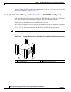
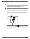
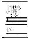
Step 6 After tightening the receptacle screws for the ground, +V, and –V DC-input leads, secure the leads to the
power supply faceplate.
Use the cable tie you saved earlier in this procedure to secure the three leads.
Note When securing the ground, +V, and –V DC-input leads to the power supply faceplate, leave a
small service loop in the ground lead to ensure that it is the last lead to disconnect from the power
supply if a great deal of strain is placed on all three leads. (See Figure 7-27.)
Step 7 Restore current to the –V and +V leads.
Note For the Cisco 7200 VXR routers:
– Each DC-input power supply operating at 24 VDC requires a minimum of 19A service.
– Each DC-input power supply operating at 48 VDC requires a minimum of 13A service.
– Each DC-input power supply operating at 60 VDC requires a minimum of 8A service.
This product relies on the building’s installation for short-circuit (overcurrent) protection.
Ensure that a listed and certified fuse or circuit breaker, 35A minimum 60 VDC, is used on all
current-carrying conductors. Site wiring and circuit breakers need to be sized to accommodate
the maximum values for safety reasons.
Step 8 Repeat Step 1 through Step 7 if a second power supply is installed.
1 0.55 in. (14 mm)
57019
1