


5-20
Network Processing Engine and Network Services Engine Installation and Configuration
OL-4448-12
Chapter 5 NPE-G1 Overview
Fiber Optic Cleaning Information
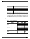
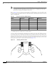
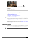
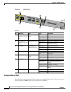
RJ-45 Auxiliary Port Signals and Pinouts
Table 5-12 lists the RJ-45 auxiliary port signals for the NPE-G1.
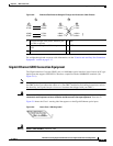
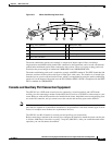
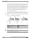
Fiber Optic Cleaning Information
We strongly recommend cleaning all optical fiber connections before reconnecting optical cables to
equipment. For information about cleaning optical connectors, see the
Inspection and Cleaning
Procedures for Fiber-Optic Connections document and the Compressed Air Cleaning Issues for
Fiber-Optic Connections document.
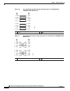
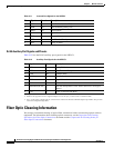
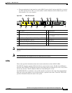
Ta ble 5-11 Console Port Signals for the NPE-G1
Pin
1
1. Any pin not referenced is not connected.
Signal Direction Description
1 CTS Out Clear To Send (tracks RTS)
2 DSR Out Data Set Ready (always on)
3 RXD Out Receive Data
4 GND — Signal Ground
6 TXD In Transmit Data
7 DTR In Data Terminal Ready
8 RTS In Ready To Send
Ta ble 5-12 Auxiliary Port Signals for the NPE-G1
Pin
1
1. Any pin not referenced is not connected.
Signal Direction Description
1 RTS Out Ready To Send
2 DTR Out Data Terminal Ready
3 TXD Out Transmit Data
4 RING
2
2. RING is not supported on Cisco-supplied adapters. To use this pin, you must create a customized cable.
In Ring Indication
5 GND — Signal Ground
6 RXD In Receive Data
7
3
3. Pin 7 can be used as a DCD input for connection to a modem. The RJ-45-to-DB-25F adapter maps DCD to this pin when
used with a straight-through cable.
DSR/DCD(RLSD) In Data Set Ready/Data Carrier Detect (Receive Line Signal
Detect)
8 CTS In Clear To Send (tracks RTS)